Basic Electrical and Electronics Engineering: Unit V: Measurements and Instrumentation
Single Phase Induction Type Energymeter
Construction, Operation Principle, Diagram, Torque equation, Error, Advantages, Disadvantage
Energy is the total power consumed or delivered over a period of time.Energy = power × time
SINGLE
PHASE INDUCTION TYPE ENERGYMETER
Energy
is the total power consumed or delivered over a period of time.
Energy
= power × time
=
0∫t VI cos ϕ dt; watt second (or) Joule.
kilowatt
hour is the power delivered at an average rate of 1000 watts for one hour.
Energy
consumed can be measured by induction type energymeter.
Induction
type energymeter consist of four main systems. They are 1. Driving system, 2.
Moving system, 3. Braking system and 4. counting system. These are explained as
follows:
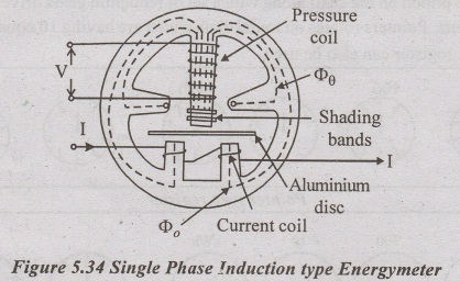
1.
Driving system:
It
is comprised of two electromagnets with silicon steel laminated core. coil of
one of the electromagnet is split into two halves and excited by load current.
It is also called as current coil. This coil forms the series magnet. The coil
of another electromagnet is connected across the supply and carries the current
proportional to the supply voltage. It is also called as pressure coil. This
coil forms the shunt magnet. Adjustable copper shadding bands are introduced at
the central limb to bring the flux produced by shunt magnet exactly in
quadrature (90').with the applied voltage.
2.
Moving system:
It
is comprised of an aluminium disc mounted on the light alloy moving shaft.
Aluminium disc is placed in a air gap between the two electromagnets (series
and shunt). Sleeve pin type bearing forms the upper suspension. Pivoted
Jewelled bearing forms the lower suspension. A pinion interconnects the shaft
with the counting mechanism.
In
floating shaft type, small magnets are used at each end to bear the shaft.
3.
Braking system:
Permanent
magnet is placed at the edge of the Aluminium disc. It provides the damping or
breaking torques. This torque is adjusted by adjusting the permanent magnet to
different radial positions.
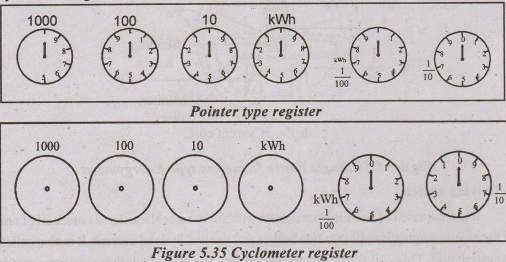
4.
Counting System / Registering mechanism:
This
system is used to continuously record the revolutions made by the moving
system. The pinion on the shaft along with a set of reduction gears drives a
series of 5 or 6 pointers. Pointers rotates on round dials which are having 10
equal divisions. Cyclometer register can also be used.
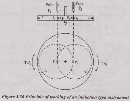
Principle:
Two
fluxes ϕ1 and ϕ2 are produced by the currents flowing in
the coils (C.C and P.C) of the instrument.
These
two alternating fluxes ϕ1 & ϕ2 which cut the disc.
flux
ϕ1 produces the eddy current i1
flux
ϕ2 produces the eddy current i2
Two
fluxes produces two eddy current which inturn induces two torques.
First
torque is produced by the interaction of ϕ1 with i2
Second
torque is produced by the interaction of ϕ2 with i1
Total
torque = Sum of two torques.
This
net torque tends to rotate the aluminium disc.
Theory
and Operation:
V
= applied voltage
I
= Load current
ϕ
= Phase angle of load
Δ
= phase angle between supply voltage and pressure coil flux
f
= frequency
Ip
= Pressure coil current
z
= impedance of eddy current paths.
Eep
= eddy emf induced by flux ϕp
Ees
=eddy emf induced by flux ϕs
∞
= phase angle of eddy current paths
Iep
= eddy current due to flux ϕp
Ies
= eddy current due to flux ϕs


Due
to large number of turns P.C winding is highly inductive. P.C current Ip
is directly proportional to the supply voltage and lags by a few degrees less
than 90. This is because the P.C winding has small resistance and iron losses
in the magnetic circuit.
ϕpt
is the flux produced by Ip. This flux is divided into two, ϕg
and ϕp. ϕg flows across the side gaps and occupies the
major portion of the flux. Reluctance of ϕg path is small. ϕp's
magnitude is small because its reluctance path is large.
ϕp
is alternating in nature. ϕp is in phase with I, and directly proportional
to Ip.
ϕp
produces eddy emf, Eep which inturn produces eddy current Iep.
ϕp goes along with aluminium disc and responsible for driving
torque.
Load
current is inphase with ϕs. ϕs produces eddy emf Ees
which inturn produces eddy current Ies
Two
torques are developed first torque is developed by the interaction of ϕs
with Ieq. Second torque is developed by the interaction of ϕp
with Ies. These two torques are in opposite direction and net torque
is the difference of these two torques.
Td
= k ϕp ϕs ƒ/z sin
(Δ - ϕ) cos ∞
Td
= k VI ƒ/z sin (Δ - ϕ) cos ∞
Td
= k1 VI sin (Δ - ϕ)
At
steady state condition, TB = Td
Breaking
torque = k2 N
k2
N = k1 VIsin(Δ - ϕ)
Speed,N
= k3 VI sin (90 – ϕ)
where
angle A=90'
Total
number of revolutions = ∫Ndt
=
k3 ∫VIcosϕ dt
=
k3. Energy.
Lag adjustment
device:
Meter
registers true energy if Δ =90° angle between ϕp and V shoud be 90.For
this P.C should have high inductance and low resistance.
core
should have small iron small iron loss. This is achieved by using lag coil.
Lag
coil is the small additional coil introduced into the limb next to the shunt coil.
It consist of few turns of thick wire.
IL
depends on reactance and resistance of lag coil.

Phase of ϕp can be adjusted by changing the mmf of shading coil either in magnitude or in phase or both.
Arrangements for
changing the mmf of the lagcoil:
There
are two methods or arrangements are used for changing the mmf of the lag coil.
These are called lag adjustments or power factor adjustments or quadrature
adjustments or inductive load adjustments.
1. Adjustable resistance:
Lag
coil circuit is closed through a low adjustable resistor.
R↑
⇒ I↓⇒ mmf of lag coil ↓ ⇒ lag angle↓
R↓I↑
mmf of lag coil ↑⇒ lag
angle ↑ and Δ becomes 90

2. Shading bands:
'Cu'
shading bands 'L1' is placed around the central limb of shunt
magnet.
Shading
bands are movable along the axis of the central limb for adjusting the mmf of
the lag coil.
If
shading band moves up, it gives more flux and increases emf as well as current
which inturn increases mmf and lag angle.
Compensations Provided in Energymeter
1.
Light load (or) friction compensation:
Moving
system cause frictional error in large manner at light loads.
To
compensate this a small torque is produced by small shading loop (L2)
placed between central limb and disc. this torque is independent of load.
2.
Creep compensation:
A
slow but continuos rotation of the aluminium disc, when only P.C is energised
and there is no current flowing through the C.C is called creep.
Creeping
is caused because of over compensation provided for friction. Friction
compensating torque is independent of load.
Creeping
is also caused by excessive voltage across the P.C, vibrations and stray
magnetic field.
Creeping
is eliminated by the two diametrically opposite holes in the disc.
The
disc will stop to rotate with one of the holes under the edge of a pole of
shunt magnet.
When
the hole is under the edge of a pole, circular eddy current path is distorted
and produces a torque which opposes the rotation of the disc. Thus the rotation
being limited to a maximum of half a revolution.
Creep
is also eliminated by attacting a small iron piece to the disc.
Braking magnet exerts a force of attraction to this iron piece and stops the disc. These compensating torque is small in nature and does not affects the deflecting torque.
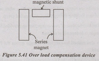
3.
Over load compensation:
Under
loaded condition, the disc rotates continuously in the field of the series
magnet, this creates a dynamically induced emf which inturn self breaking
torque in the disc.
At
high load, the meter reads low because of self braking torque.
1.To
minimize this torque, 1. Full load speed is kept small nearly equal to 40 rpm
2.
The current coil flux o, is made small compared with op.
3.
Otherwise an overload compensating device is used. Magnetic shunt provided in
this device diverts series magnetic flux, so a large portion of the flux
appears in the air gap and produces more driving torque.
4.
Voltage compensation:
Variations
in supply voltage causes error because
1.
Relationship between the shunt magnetic flux and the supply voltage is non
linear due to saturation in iron parts.
2.
ϕp causes dynamically induced emf in the disc which inturn creates
self breaking torque.
This
is eliminated by using magnetic shunt or by drilling holes in the side limbs.
Holes increases the reluctance of the side limbs of the shunt magnet.
5.
Temperature compensation:
If
temperature rises, resistance of copper and aluminium parts increases and
causes the following results.
1.
a small decrease in ϕp and Δ decreases.
2.
the torque produced by shading bands are decreased.
3.
an increase in the resistance of eddy current paths.
4.
a decrease in the angle ‘∞' of eddy current.
This
errors are high at low power factor loads. This causes the disc to run fast and
to register high.
This
is eliminated by using a temperature shunt on the breaking magnet or by using a
special magnetic material like mutemp.
mutemp
has the property of decreasing its permeability with increase in temperature.
Error:
Error
caused by the driving system are
1.
Incorrect magnitude of fluxes
2.
Incorrect phase angles and
3.
Lack of symmetry in magnetic circuits.
Errors
caused by the braking system are
1.
Variations in strength of the braking magnet.
2.
Variations in the resistance of the disc.
3.
Self braking effect of series magnetic flux and
4.
Friction of moving parts.
Advantages:
1.
Universally used for domestic and industrial ac circuits.
2.
Low friction
3.
High torque - weight ratio.
4.
Maintain accuracy over wide range of load and temperature.
Three Phase Energymeter
As
Per Blondel's Theorem, 'n' conductor system requires (n - 1) measuring elements
for the measurement of total energy. Therefore 3 phase 3 wire system uses 2
element for the measurement of total energy.
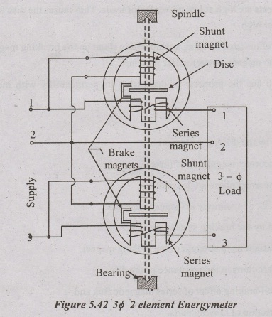
Two
element energymeter Consist of two discs. A current coil together with its
pressure coil is called as an element. Each element consist of one disc.
Magnetic shunt is provided to one or both the elements, to balance the torques
of these two elements.
Pressure
coils are connected in parallel and current coils are connected in series in
such a way that the torque produced by each element are equal and opposite in
nature with the single phase supply. Now the magnetic shunt is adjusted till no
rotation of the disc occurs.
Lag
adjustments, light load adjustments and unity power factor adjustments are done
independently for each element.
after
doing all these adjustments, the meter is connected to the three phase supply.
Two discs are mounted on the same spindle. Therefore the total deflecting
torque is the sum of the deflecting torques produced by the two elements
separately.
Basic Electrical and Electronics Engineering: Unit V: Measurements and Instrumentation : Tag: : Construction, Operation Principle, Diagram, Torque equation, Error, Advantages, Disadvantage - Single Phase Induction Type Energymeter
Related Topics
Related Subjects

Basic Electrical and Electronics Engineering
BE3251 2nd semester Mechanical Dept | 2021 Regulation | 2nd Semester Mechanical Dept 2021 Regulation

Basic Electrical and Electronics Engineering
BE3251 2nd Semester CSE Dept 2021 | Regulation | 2nd Semester CSE Dept 2021 Regulation