Basic Electrical and Electronics Engineering: Unit V: Measurements and Instrumentation
Single Phase and Three Phase Wattmeters and Energy Meters
Construction, Operation Principle, Diagram, Torque equation, Advantages, Disadvantage
Single phase power is measured by wattmeter. It gives the direct indication of power. It also takes account on the power factor.
SINGLE
PHASE AND THREE PHASE WATTMETERS AND ENERGY METERS
Single Phase Wattmeter
Single
phase power is measured by wattmeter. It gives the direct indication of power.
It also takes account on the power factor.
At
transient condition importance are given to the instantaneous power. At steady
state condition importance are given to the average value of power over a
cycle. Single phase wattmeter indicates the average value of power.
Electrodynamometer
wattmeter, ferrodynamic wattmeter and low power factor (LPF) wattmeter are used
for the measurement of single phase AC power.
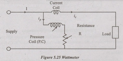
Electrodynamometer Wattmeter
It
consist of two coils,
1.
Fixed coil (or) field coil
2.
Moving coil (or) voltage coil

Fixed
coil is divided into two halves and it is connected in series with the load. It
carries the current in the circuit so it is also called as current coil (C.C).
It is made up of heavy wire. It is laminated to avoid eddy current loss.
Maximum current is limited to 20 A.
For
power measurement associated with large load current, 5A wattmeter with a
current transformer is used.
Fixed
coil is connected in series for a basic measurement range. To increase
wattmeter current range to twice its original value, C.C can be connected in
parallel. Shunts are not used for extension of current range because they canse
temperature errors.
Moving
coil is connected across the voltage. It carries a current proportional to the
voltage, a high non inductive resistance is connected in series with this coil.
This coil is called as pressure coil (P.C) and it is mounted on a pivoted
spindle. Series resistance limits the current flow through this coil.
Both
the coils are air cored. Voltage rating of wattmeter is usually limited to
600V. For higher voltage, pressure coil is designed for 110V and a potential
transformer is used along with the wattmeter.
Control
torque is produced by spring control system. Damping torque is provided by air
friction damping. Eddy current and electromagnetic damping are not used because
of weak operating force. Mirror type scale and knife edged pointer is used.
Principle:
Current
through the current coil creates a flux around it. Current proportional to the
voltage through the pressure coil creates its own flux around the coil. These
two fluxes creates a force between them. This causes a deflecting torque.
Torque equation:
instantaneous
torque of electrodynamometer instrument is
Ti
= ip ic d M/d Q
where
ip and ic are the instantaneous value of current in the
P.C and C.C respectively.
Instantaneous
value of voltage across the P.C is vp = √2 Vp sinωt
P.C
is considered as purely resistive because of its very high resistance. Current
in P.C is in phase with voltage and its instantaneous value is,
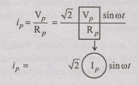
ip
=√2Ip ………(1)
current
in C.C lags the voltage in phase by an angle 'ϕ'
instantaneous value of 'I' in C.C is,
ic
= √2 Ic sin(ωt - ϕ) ……….(2)
From
(1) & (2),
Ti
= √2 Ip sinot √2 Ic sin (ωt - ϕ).dM/dQ
we
know that
sin
A sin B = ½ [cos (A-B) - cos (A + B)]
here
A = ωt and B = ωt - ϕ
Ti
= √2 Ip √2 Ic ½ [cos (ωt - ωt + ϕ) - cos (ωt + ωt - ϕ)].dM/dƟ
Ti
= Ip Ic [cosϕ - cos (2ωt - ϕ)].dM/dƟ
From
the above equation it is clear that the component of power varies as twice the
frequency of current and voltage.
Averge
deflecting torque, Td = 1/T 0∫T Ti d
(ωt)
Td
= 1/2π 0∫2 π
Ip Ic [cosϕ - cos (2ωt - ϕ)].dM/dƟ . dωt
Td
= Ip Ic cosϕ.dM/dƟ
Tc
= kƟ by spring control.
At
final steady state, Tc = Td
kƟ
= Ip Ic cos ϕ dM/dƟ
Ɵ
= VI/Rp cos ϕ dM/dƟ . 1/k
Ɵ
= ﴾k1
. dM/dƟ﴿. VI cos ϕ
deflection,
Ɵ ∞ power
Scale
is uniform over the range in which dM/dƟ is constant.
Advantages:
1.
It indicates average value of power
2.
Accurate reading
3.
Damping is effective
4.
No hysteresis error.
Disadvantage:
1.Td
is small
2.
Error occurs due to the inductance of the P.C.
3.
Not suited for low power factor circuits
Ferrodynamic Wattmeter
In
this type of wattmeter, core is made up of iron. Low loss iron increases T by
increasing flux density.
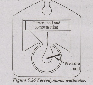
Fixed
coil is wound on a laminated core. core is having pole pieces. Moving coil is
placed over a hook shaped pole piece.
The
iron losses make the flux de produced by the C.C to lag behind 'I' by an angle
'∞'.
deflection,
Ɵ = Ip I dM/dƟ cos (ϕ + ∞ - β)
Ɵ
= C1 dM/dƟ VI cos (ϕ + ∞ - β)
If
∞ = β, Ɵ = C1 dM/dƟ VI cos ϕ
Ɵ
= C2 P
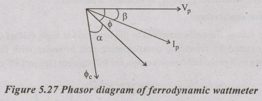
Where
C1 & C2 are constants, thus the phase angle error
will be zero. creep occurs in P.C because the P.C tries to take up a position
where it links with maximum flux. Creep is a small but continuous change in
position of the P.C on the hook when only the P.C is energised. (C.C is not
energised). Creep is eliminated by using compensating coil.
In
order to make a = β, 'β' angle should be increased, for this inductance of P.C
should be increased. This high inductance is achieved by unifilar winding of
series resistor. This high inductance and iron losses causes error, in reading.
To eliminate this error a capacitor is used in parallel to the moving coil and
a part of its series resistance.
Advantage:
1.
Less sensitive to external magnetic field
2.
High Td which is proportional to average power
3.
Scale is upto 270.
Disadvantage:
1.
Error due to non linearity of magnetization curve
2.
Large eddy current and hysteresis losses in core cause errors.
Low Power Factor Wattmeter
Ordinary
electrodynamometer wattmeter is not suited for the measurement of in low
powerfactor circuits because 1. it has low Td value and 2.
inductance of P.C creates large errors at low power factors.
So
some special changes or compensations are provided to ordinary
electrodynamometer wattmeter to make it suitable for low power factor circuits.
Such changes are listed below.
1. Pressure coil
current (Ip):
P.C
circuit is designed with low resistance, so this increases the current flows
through the P.C and increases Td.
Ip
in LPF wattmeter ~ 10 (Ip in ordinary wattmeter)
2. Wattmeter
connection:
Power
loss in the coil connected to the load side is high. (either C.C or P.C). This
is eliminated by providing compensating coil in series with the P.C. This
compensating coil provides compensation for P.C current (Ip) in LPF circuit.

3. Inductance of
pressure coil:
Inductance
of P.C cause error in readings. This error is equal to VI sinϕ tan β The value
of ϕ is large in case of LPF circuit and this automatically results in very
high error.
This
error is eliminated by a capacitor placed in parallel to a portion of series
resistor connected with the P.C.
4. Small control
torque:
LPF
wattmeter is designed to have a small control torque. This small Tc helps
for full scale deflection in LPF.
Thermocouple Wattmeter
In
this circuit, two thermocouples are connected in such a way that they sense the
heat generated by the two heter elements.
A
galvanometer is connected between these two thermocouple

Emf
across the galvanometer = e1 - e2
where
e1 is the emf generated by the first thermocouple. and e2
is the emf generated by the second thermocouple.
RH
is the resistance of the heater element.
Td
∞ vi (instantaneous power).
In
this type two thermocouples are assumed to be identical. Thermal watt converter
is used for measuring power in AC circuits.
Thermal
watt converter consist of two heater element, two thermocouple, current and
potential transformer arrangement. The plain arrowmark indicates the current
flows from C.T and the flagged arrowmark indicates the current flows from P.T.
In heater A, two currents flows in the same direction (S2). In
heater B two currents flows in the opposite direction (D2).
Thermocouple A & B senses the heat produced by the heater A & B
respectively.
From
the phasor diagram,
S2
= V2 + I2 + 2VI cosϕ
D2
=V2 + I2 - 2VI cosϕ
S2
- D2 = 4 VI cos ϕ
power
= ¼ (S2 - D2)
where
k is the constant.
voltage
indicated by the millivoltmeter is E ∞ K (S2 - D2)
E
∞ power

Hall Effect Wattmeter
When
a current is allowed to pass through a conductor element, at the same time a
magnetic field is applied perpendicular to the direction of current flow. A
voltage is developed at the transverse side of the conductor. This effect is
called hall effect, and the voltage developed is called hall voltage. This hall
effect is used for the measurement of power.
Hall
effect wattmeter is also called as hall effect multiplier. In this current is
passed through the current coil and it produces a magnetic field perpendicular
to the hall effect element. A current i proportional to the voltage is passed
through the hall effect element. The current is limited by R. The output
voltage is given by
VH
= KH ip B/t
Where
KH is the hall co-efficient, B is the flux density and t is the
thickness of the hall element.
Here
B ∞ i and
ip
∞ v
VH
∞ V.i
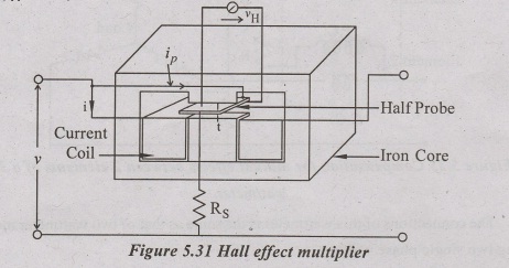
output
voltage is proportional to the instantaneous power. The voltmeter connected at
the output terminals is calibrated interms of power. The main advantage of this
method is : its output can be used for further processing or for control
applications.
Three Phase Wattmeter
A
electrodynamometer type three phase wattmeter consists of two elements. A
current coil along with its pressure coil is called as an element. Two moving
coils (P.C's) are mounted on the same spindle.
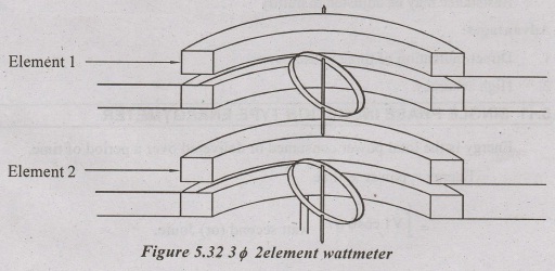

The
connections of this wattmeter is the same as that of two wattmeter method using
two single phase wattmeters.
Here
Td of Ist element ∞ P1
Td
of IInd element ∞ P2
Total
deflecting torque o P1 + P2 ∞ power.
Error
occurs if any mutual interference exist between the two elements. To eliminate
this a laminated iron shield may be used or a compensation is provided by using
weston's method.
Resistance
may be adjusted to nullify the mutual interference effect.
Advantages:
1.
Direct indication of three phase power.
2.
High accuracy.
Basic Electrical and Electronics Engineering: Unit V: Measurements and Instrumentation : Tag: : Construction, Operation Principle, Diagram, Torque equation, Advantages, Disadvantage - Single Phase and Three Phase Wattmeters and Energy Meters
Related Topics
Related Subjects

Basic Electrical and Electronics Engineering
BE3251 2nd semester Mechanical Dept | 2021 Regulation | 2nd Semester Mechanical Dept 2021 Regulation

Basic Electrical and Electronics Engineering
BE3251 2nd Semester CSE Dept 2021 | Regulation | 2nd Semester CSE Dept 2021 Regulation