Basic Electrical and Electronics Engineering: Unit I: Electrical Circuits
Nodal Analysis
Steps, Example Figure with Equation | Electrical Circuits
The nodal method is used to analyze multisource circuits. In this method, Kirchoff's current law is applied at various nodes in an electric circuit.
NODAL ANALYSIS
The nodal method is used to analyze multisource circuits. In this method, Kirchoff's current law is applied at various nodes in an electric circuit. Node is defined as junction (or) joining point of two or more components.
In nodal method, one node is selected as a reference node, with respect to which the voltage at all other nodes are measured. Thus the reference node acts as ground for the circuits.
The first step is to convert all voltage sources to current sources. The second step is to identify all the principal nodes in the circuit and to choose a reference node. To select the reference node as the one having the most component connected to that node. All the nodes except the reference node are numbered and their corresponding voltages are designated as V1,V2,…. etc. The reference node and other nodes are indicated as shown in the circuit.
Steps to be followed,
1. Select one major nodes as the reference node and assign each of the (n-1) remaining nodes its own unknown potential, with respect to the reference node.
2. Assign branch current to each branch.
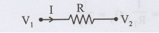
3. Express the branch currents in terms of the node potentials
I = V1 – V2/R
4. Write the current equation at each of the n-1 unknown nodes.
5. The current equations are a set of simultaneous equations in the unknown node voltages.
6. Solve for the unknown voltages and the branch currents.
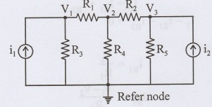
Consider the circuit shown in figure
The circuit diagram consists of three nodes. It is possible to write (n-1) equations. Applying KCL at node 1
I1 = IR1 + IR3
I1 - IR1 - IR3 = 0
where
IR1= V1/R1
IR3 = V1- V2/R3
I1 - V1G1 –V1G3 + V2G3 = 0
I1 - V1(G1 + G3) + V2G3 = 0
I1 = V1(G1 + G3) - V2G3 ……….(1)
Where
G1 = 1/R1,G3 = 1/R3
Consider node 2
I2+ IR3 - IR2 = 0
Where
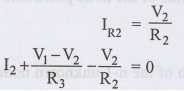
I2 + V1G3 − V2 G2 − V2 G3 = 0
I2 + V1G3 − V2 (G2 + G3) = 0
I2 = V2 (G2 + G3) − V1G3 …………(2)
I1 = V1(G1 + G2) − V1⁄2G3
Form the matrix by using equ (1) & (2)
The generalised node equations can be written as
[G] [V] = [I] …………(3)
where
[G] - node conductance matrix
[V] - column matrix of the node voltages with respect to the reference
node
[I] - column matrix of input currents
Inspection method:
Step 1:
Convert all the voltage source into current sources.
Step 2:
The conductances of all branches connected to nodes 1 are added and denoted by G11 G11 is the self conductance of node 1.
Step 3:
All the conductances connected to nodes 1 and 2 are added and denoted by G12, G12 is mutual conductance of node 1 and 2. G12 is written with -ve sign. If no conductance is connected between nodes 1 and 2 then G12 = 0, G12 = G21"
Step 4:
I1 denotes the value of the current to node 1 and is written on the right hand side of the equation the sign I1 is positive if it is flowing towards node I1, otherwise it is -ve. If no current source is connected to node 1 then I1 = 0.
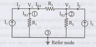
Consider the following circuit.
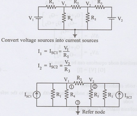
This circuit consists of two nodes 1 and 2 and common node (Ref node).
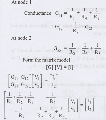
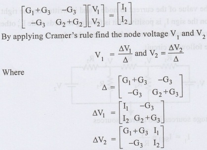
By solving the above matrix, we can find nodal voltages V1 and V2.
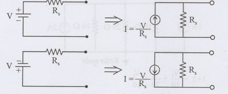
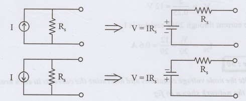
Source transformation:
Voltage source to current source
If a voltage source has a resistance connected in series, it can be transformed into an equivalent current source with the resistance connected in parallel.
Current source to voltage source
If a current source has a resistance connected in parallel, it can be transformed into an equivalent voltage source with the resistance connected in series.
Basic Electrical and Electronics Engineering: Unit I: Electrical Circuits : Tag: : Steps, Example Figure with Equation | Electrical Circuits - Nodal Analysis
Related Topics
Related Subjects

Basic Electrical and Electronics Engineering
BE3251 2nd semester Mechanical Dept | 2021 Regulation | 2nd Semester Mechanical Dept 2021 Regulation

Basic Electrical and Electronics Engineering
BE3251 2nd Semester CSE Dept 2021 | Regulation | 2nd Semester CSE Dept 2021 Regulation