Basic Electrical and Electronics Engineering: Unit V: Measurements and Instrumentation
Moving Iron (MI) Instrument
Construction, Operation Principle, Types, Diagram, Torque equation, Advantages, Disadvantage
It is the commonly used, accurate instrument for both AC and DC measurement. It is divided into two types 1. attraction type and 2. Repulsion type.
MOVING IRON (MI) INSTRUMENT
It
is the commonly used, accurate instrument for both AC and DC measurement. It is
divided into two types 1. attraction type and 2. Repulsion type. Moving Iron
Instrument consist of a stationary coil which is excited by the current or
voltage under measurement. It also consist of a plate or vane of soft iron in
case of attraction type in case of repulsion type, two vanes are present.
Vane
forms the moving element of the instrument and moves in a magnetic field
produced by a stationary coil.
Principle:
Supply
is given to the stationary coil it becomes Electromagnet vane moves to increase
the flux of the electromagnet because vane tries to occupy a position of
minimum reluctance.
Inductance
α 1/reluctance
Thus
a force is developed for getting high inductance. This force gives the
deflecting torque.
Types:
Attraction type MI instrument
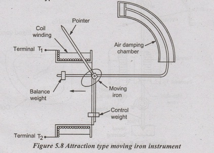
The
flat stationary coil forms the narrow slot like opening. moving element is a
flat disc or plate.
When
current flows through the coil, magnetic field is produced around the coil.
moving Iron moves from weaker field to stronger field side.
For
control torque this instrument uses spring. In panel type, vertical mounted
case uses gravity control for T. Damping is provided by air friction damping.
Repulsion Type
Two
vanes are present inside the stationary coil, one vane is fixed and another
vane is movable.
Both
vanes are similarly magnetised when the current flows through the stationary
coil, So repulsion occurs between the two vanes.
This
type is divided into two
1.
Radial vane type and
2.
Co-axial vane type.
In
radial vane type, vanes are radial strips of Iron.

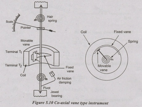
In
co-axial vane type, vanes are sections of co-axial cylinders.
Tc
is provided by spring and by gravity control for vertically mounted instrument.
Air
friction damping is used.
Eddy
current damping is not used because operating magnetic field is very weak.
Torque
Equation:-
Torque
equation is derived from the energy relations.
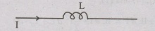
Normally
current flows through the coil
Now
a small increment in current is supplied to the coil, it result in a small
increment in deflection.
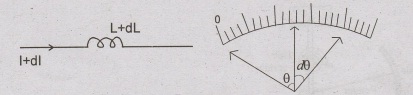
Mechanical work done = Td dƟ ………(1)
emf,
e = d/dt (L I)
e
= I dL/dt + L dI/dt ………(2)
Electrical
energy supplied is given by, multiply I. dt on both sides of equation (2),
eI
dt = I2 dL/dt. dt + L I dI/dt. dt
eI
dt = I2 dL + L I dI ……….(3)
Stored
energy changes from 1/2 I2 L to 1/2
(I
+ d I)2 (L + dL)
Change
in stored energy is
1/2 (I2 + 2 I dI + d I2
(L + dL)
Neglecting
second and higher order terms,
IL
dI + 1/2 dL ……..(4)
By
the principle of conservation of energy,
Electrical
energy supplied = increase in stored energy + mechanical work done.
From
equation (3), (4) and (1),
I2
dL + I L dI = IL dI + 1/2 I2 dL + Td. dƟ
Td
. dƟ = I2 dL – 1/2 I2 dL
Td
.dƟ = ½ I2 dL
Td
= ½ I2 dL/dƟ ……….(5)
control
torque is provided by spring
Tc
= K Ɵ …………(6)
For
final steady deflection, Tc = Td
..
from equation (5) and (6),
KƟ
= ½ I2 . dL/dƟ
Deflection,
Ɵ = ½ I2/K . dL/dƟ
deflection
is directly proportional to the square of the rms value of the measuring
current. scale is nonlinear.
Torque
is unidirectional, so MI instrument is not polarity sensitive.
Error
in MI instrument:
(i) Error occurs when used for both
AC and DC measurement:
1.
Varying flux density causes hysteresis error. it is eliminated by using small
Iron pieces.
2.
Temperature error, it is eliminated by swamping Resistance.
3.
Operating field is weak and it cause stray magnetic field error. itis
eliminated by a thin iron shield placed over the working parts.
(ii) Error occurs when used for ac
only:
1.
Frequency error: it is due to change in reactance of
working will, as a result of this error deflection for a given voltage will be
low at high frequency than at loco frequency.
This
error is minimized by providing frequency compensation.
Frequency
compensation is done by connection a capacitor 'C' parallel with the series
resistor 'Rs'.

This
is possible only upto 125HZ.
2.
Eddy carrent error:
Eddy
current developed in the moving iron parts causes error.
Extension
of meter range:
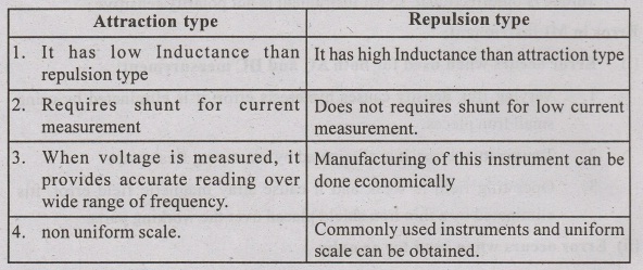
Comparision between Attraction Type and Repulsion Type MI instrument
Advantage:
1.
Used for both dc and AC measurement.
2.
Less frictional errors.
3.
Low cost compared to other ac measuring instruments.
4.
Accuracy
5.
Robustness.
Dis-advantage:
1.
Non uniform scale
2.
It suffers from hysteresis and eddy current error.
3.
Calibration is different for AC and DC operation.
Basic Electrical and Electronics Engineering: Unit V: Measurements and Instrumentation : Tag: : Construction, Operation Principle, Types, Diagram, Torque equation, Advantages, Disadvantage - Moving Iron (MI) Instrument
Related Topics
Related Subjects

Basic Electrical and Electronics Engineering
BE3251 2nd semester Mechanical Dept | 2021 Regulation | 2nd Semester Mechanical Dept 2021 Regulation

Basic Electrical and Electronics Engineering
BE3251 2nd Semester CSE Dept 2021 | Regulation | 2nd Semester CSE Dept 2021 Regulation