Basic Electrical and Electronics Engineering: Unit V: Measurements and Instrumentation
Instrument Transformers
Construction, Operation Principle, Equivalent Circuit Diagram, Characteristics, Advantages, Applications
Instrument transformer is used for the measurement of voltage, current, power and energy. Measuring instruments are used along with transformer operation is called Instrument transformer.
INSTRUMENT TRANSFORMERS
Instrument transformer is used for the measurement of voltage, current, power and energy. Measuring instruments are used along with transformer operation is called Instrument transformer. Its working is same as that of ordinary transformer. Direct measurement of very large current and voltage is not possible. In that places, instrument transformer is used to step down the current and voltage suitable for measurement with ordinary meters.
There are two types of Instrument transformers. They are,
1. Current Transformer (C.T) and
2.Potential Transformer (P.T)
Shunt and Multipliers are used for the extension of meter range but this can be done upto a certain limit, because they are having the following disadvantages.
Disadvantages of shunt:
1. Shunt gives inaccurate result in AC circuits.
2. Current division in shunt and meter depends on reactance to resistance ratio of two paths. Time constant of two paths should be equal for equal division of current. It leads to the usage of separate shunt for each meter.
3. It is used upto few 100A beyond this limit it causes large power consumption.
4. For large current value providing insulation is difficult.
5. Accuracy is only for limited frequency range.
6. Because of its usage, measuring instrument is not electrically isollated.
Disadvantages of Multiplier:
1. Multiplier is used upto 1000V beyond this limit cause large power consumption.
2. For large voltage value providing insulation is difficult and costly.
3. Reduction of distributed capacitance to avoid shunt capacitance in multiplier is also difficult.
4. Because of its usage, measuring instrument is not electrically isollated.
Transformation ratio (R):
Transformation ratio, R = | Primary Phasor |/| Secondary Phasor |
In C.T, R = Primary winding current/Secondary winding current and
In P.T, R = Primary Winding Voltage/Secondary Winding Voltage
Nominal ratio (K):
In C.T, Nominal ratio, Kn = rated primary winding current/rated secondary winding current
and in P.T, Kn = rated primary winding voltage/rated secondary winding voltage
Nominal ratio is marked on the Instrument Transformer.
Turns ratio (n):
In C.T, n = number of turns of secondary winding/number of turns of primary winding
In P.T, n = number of turns of primary winding/number of turns of secondary winding
Ratio Correction Factor (RCF):
RCF = Trasformation ratio/Nominal ratio = R/Kn
Burden:
Burden is the circuit or load connected across the secondary winding terminals of the instrument transformer. It is expressed in volt ampere at the rated secondary winding voltage.
Total secondary winding burden
= (Secondary winding induced voltage)2/﴾Impedance of secondary winding circuit including Impedance of secondary winding﴿ for a P.T
= (Secondary winding current)2 × ﴾Impedance of secondary winding circuit including Impedance of secondary winding﴿ for a C.T
Secondary winding burden due to Load
= (Secondary winding induced voltage)2/(Impedance of Load on secondary winding) for a P.T
= (Secondary winding current)2 × (Impedance of Load on secondary winding) for a C.T
Current Transformer (C.T)
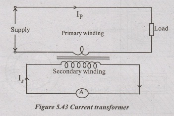
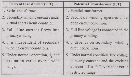
It is used for the measurement of large magnitude of current. It has less number of turns in the primary winding. The primary winding is connected to the high current circuit in such a way that the current to be measured flows through it and it is in series with the load.
C.T is also called as series transformer. It step down the current value suitable for standardized meter by transformer action.
Amp-turns on the primary side = Amp-turns on the secondary side.
eg: 500 A × 1 turn = 5 A × 100 turns.
The secondary winding has very small load impedance provided by the current coil of the ammeter connected across it.
The flow of current in the secondary winding is in an opposite direction to the flow of current in the primary winding.
Construction of C.T
C.T is of two types,
1. Wound type:
Secondary winding is first wounded on bakelite former or bobbin above this suitable insulation is provided.
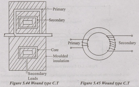
Primary winding is wounded separately above secondary. It is used for low current application.
2. Bar type:
Primary winding consists of a bar of suitable size and it forms an integral part of the transformer. Insulation is provided by Bakelite paper tube or resin.
External diameter is made large to eliminate corona effect. Bar type is used for high current applications (>100A).
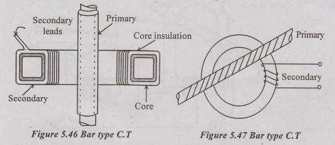
Bar type is similar to Ring type transformer.
In C.T Laminated stack takes greater crosssection area of core to keep the reluctance low.
This minimizes magnetizing current.
Secondary winding utilize whole winding length of core.
Insulation is provided to withstand high peak voltages Peak voltages is formed if secondary is open when primary is energized.
Position of primary and secondary winding coil are adjusted to eliminate primary winding short circuit current.
Windings are placed as close as possible to reduce secondary winding leakage reluctance.
Secondary winding material: Copper
Primary winding material: Copper strip
Insulation: tape or varnish for low voltages, oil immersed or compound filled for high voltages (>7KV)
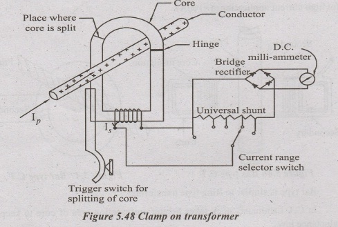
Clamp on transformer:
This type of C.T is also called as Split core transformer. Trigger switch is used to split the core and the core is clamped on to the place where high current is to be measured. The main advantage of this type is the circuit is not disturbed for the series insertion of C.T with the line current.
Equivalent Circuit of a C.T
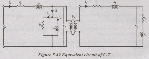
Ip = Primary winding current,
Ip = Secondary winding current,
Vs = Voltage at the secondary winding terminals,
Vp = Voltage at the primary winding terminals,
rp & xp = Resistance and reactance of the primary winding respectively,
rs & xs = Resistance and reactance of the secondary winding respectively,
re & xe = Resistance and reactance of external burden i.e., meters, current coils, etc. including leads respectively,
Np = number of primary winding turns,
Ns = number of secondary winding turns.
Ep = Primary winding induced voltage,
Es = Secondary winding induced voltage,
Ꮎ = Phase angle of the transformer,
ϕ = Working flux of the transformer,
δ = Angle between secondary winding induced voltage and secondary winding current.
α = Phase angle of total burden including impedance of secondary winding.
= tan-1 (xs + xe /rs + re)
Δ = Phase angle of secondary winding Load
= tan-1 (xe / re)
I0 = Exciting current.
Im = Magnetizing component of I0
Ie = Loss component of I0
∞ = Angle between exciting current I0 and working flux ϕ.
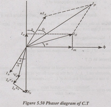
ϕ is taken as the reference vector. The induced voltage E lags by 90°. Exciting current I0 has two components.
1. Magnetizing component, Im
2. Loss component, Ie
The amount of I0 drawn depends upon the core material.
Errors in C.T
1. Transformation ratio (R) is not equal to turns ratio. 'R' is not a constant value but it depends on Im,Ie,Is and the power factor of the circuit. This indicates that Is is not a constant fraction of Ip. This causes an error called Ratio error.
% Ratio error = Nominal ratio - actual ratio × 100/ actual ratio
= kn - R× 100/ R
Transformation ratio (or) actual ratio (R) is given by.
R ≈ n + I0/Is sin (δ+ a)
R ≈ n + Ie/Is → approximate formula (1)
2. In power measurement, the phase angle of Ip should be exactly 180° from that of Ip. When Is is reversed, it differs in phase with Ip that angle is called the phase angle (Ɵ) of the transformer.
The error caused due to I not being 180° out of phase with Ip is called phase angle error.
Phase angle Ɵ = 180/π [ Im cosδ - Ie sin δ/nIs ] in degree.
and Ɵ ≈ 180/ π (Im /nIs)degrees (or)
Ɵ ≈ 180/ π (Im /Ip)degrees → approximate formula (2).
Approximate formula's (1) and (2) shows that ratio error depends on Ie and phase angle error depends on Im.
Characteristics of C.T
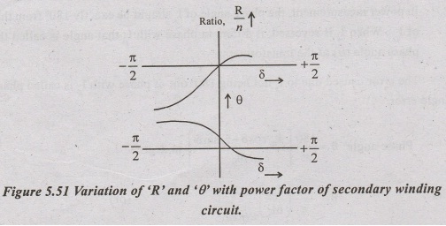
1. Effect of power factor of secondary winding burden on errors:-
Ratio error: For all inductive burden, Is lags Es and δ is +ve. In this condition, R>n. For capacitive burden, Is leads Es and δ is -ve. In this condition, R<n for δ approaching -90°.
Phase angle error: For inductive burden, δ is +ve for small values of 'δ' and Ɵ is -ve for high inductive burden and δ approaching +90°.
For capacitive burden Ɵ is always +ve and δ is -ve.
The magnitude of secondary impedance is assumed as constant.
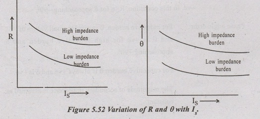
2. Effect of change of Ip:
If Ip changes Is also changes proportionally.
At low values of Ip, Im and Ie are a great proportion of Ip and errors are greater.
If Ip increases, Is also increases results in the decrease of ratio error and phase angle error.
3. Effect of change in burden:
An increase in burden means an increase in Volt-Ampere rating. This call for an increase in Es which can be generated by an increased flux and flux density.
Both Im and Ie are increased. This causes the error to increase.
4. Effect of change in frequency:
An increase in frequency causes proportionate decrease in flux density.
CT is rarely used at a frequency which is very different from the designed frequency.
Methods to Reduce Errors in C.T
In order to reduce ratio error and phase angle error, the components I and I must be kept at low value.
This is possible by the following methods:
1. Core material and design
The material used for the construction of the core should have high permeability.
Core should have short magnetic path and large cross section area.
The core materials are divided into three categories. They are
1. Hot rolled silicon steel.
2. Cold rolled grain oriented silicon steel and
3. Nickel iron alloys.
The materials having high permeability at low flux densities are
Mumetal- 76% Nickel, 16% Fe
Permendur- 49% Co and 49% Fe (high saturation density)
Hi pernik- 50% Fe and 50% Ni
The core should possess minimum number of joints. For this ring type and spiral type cores are used.
2. Primary winding current ratings
C.T with a rated current of 500 A or more are used with a single turn primary. Nowadays, because of the advancement in technology, 100A current are used with the single turn primary winding.
3. Leakage reactance also increases the ratio error
Therefore in order to reduce the leakage reactance in secondary winding, two windings are placed very close to each other.
4. Use of shunt
If the Is value is too large, it may be reduced by using a shunt across the primary or the secondary winding. This is suited only for a particular value. It reduces phase angle error.
5. Turns compensation
The number of turns of the secondary winding can be reduced by one or two. The C.T in this case is called compensated C.T. This correction is suited only for a particular value of current and burden. It reduces ratio error.
6. Wilson compensation method
In this method, few turns of wire is introduced in series with the secondary winding and it is passed through a hole in the core. It is called as an auxiliary secondary turns. The action of this turns are similar to shading bands. It reduces phase angle error.
7. Two stage design
This method uses another C.T to correct the error occurs in the Is of first C.T This method is applied to energy meters.
Effect of Open the Secondary Winding Circuit
In ordinary transformer, primary winding current (Ip) depends on the current flowing in the secondary winding. But in case of C.T, Ip does not depends on the secondary winding circuit conditions. Ip is the line current flowing in the circuit where C.T is connected for measurement.
Under short circuit or normal operating condition (Ammeter or relay is connected to the secondary winding of C.T). Both the primary and the secondary winding produces mmf. These mmf's opposses each other. Secondary winding mmf is smaller than primary winding mmf. The resultant mmf is small and it causes low flux to be produced in the core. As a result small amount of voltage is induced in the secondary winding.
Under open circuit condition, the secondary winding mmf is reduced to zero. This causes the resultant mmf equals to the primary winding mmf. A large amount of flux is produced in the core. As a result high voltage is induced in the secondary winding which causes damage to the insulation and also to the operating personnel.
It also creates large amount of eddy current and cause large hysteresis losses. Due to this-transformer may be overheated and completely damaged. To reduce this core may be permanently magnetised but this gives large ratio and phase angle error.
A short circuiting link or switch is provided at the secondary winding side of the C.T. This switch is activated when some work has to be done on the secondary winding side while its primary winding is energised.
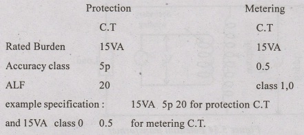
C.T Specification
C.T is specified in terms of its rated burden at rated current, an accuracy class and Accuracy Limit Factor (ALF).
An upper limit beyond which accuracy is not guaranteed is called accuracy limit factor (ALF).
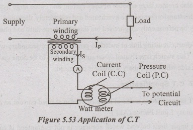
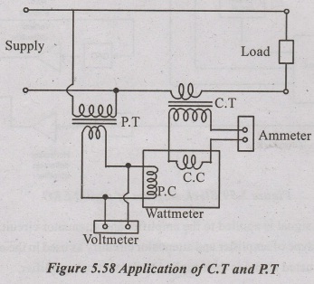
Application of C.T
C.T is used for the measurement of current and power. It is shown in the diagram.
The Ip is the line current controlled by the load and not by the secondary winding burden.
Ammeter and current coil of the wattmeter are connected directly to the secondary winding for the measurement of current and power respectively.
One of the terminals of secondary winding is earthed for safety.
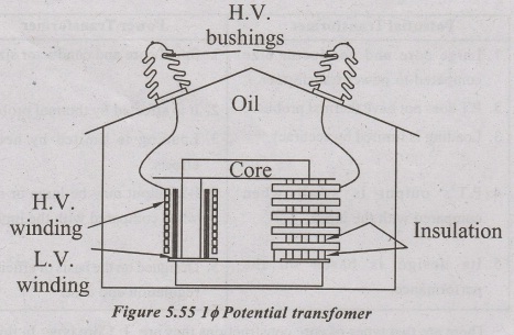
Potential Transformer (P.T)
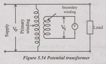
It is used for the measurement of high voltage by means of low range voltmeters.
It is also used for energising the potential coil of wattmeter and energymeter.
The primary winding is connected with the high voltage and it has more number of turns. P.T is also called as parallel transformer. The secondary winding has less number of turns when compared with the primary. It steps down the voltage between 110V to 120V.
P.T is similar to power transformer with some differences, they are tabulated as follows.
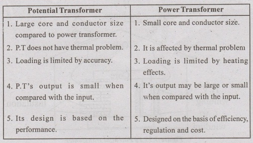
There are two types of core constructions they are 1. Core type: In this type, the winding is placed on one of the shorter limb. This type is used for high voltage transformers.
2. Shell type: This type is used for low voltage transformers.
In order to minimize the leakage reactance both the windings are placed co- axial in nature.
Secondary winding is wounded first over the core. A suitable insulation is applied above the secondary winding. The various types of insulation are as follows:
Hard fibre separators for between coils, cotton tape and varnished cambric for coil construction, compound filled insulation for low voltage P.T, oil immersed insulation for P.T above 7KV dry type and porcelain insulation for P.T upto 45KV.
Primary winding is wounded next to the secondary winding. Primary winding is of single turn for low voltage and it is divided into halves (short coils) for high voltage operation.
Oil filled bushings are used for oil filled P.T's. It minimizes the overall size of the transformer.
There are two designs are developed to eliminate this bushings.
1. Insulated casing: In this transformer is built wholely in an oil filled high voltage insulator.
2. Moulded rubber: In this design, bushings are made up of moulded rubber. This eliminates the problem caused by porcelain breakage.
These designs are aimed to measure the line to ground voltages in a three phase system. And also reduces the transformer's cost.
Equivalent Circuit of a P.T
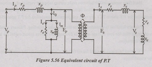
Ip is primary winding current.
Is = Secondary winding current
Np = Primary winding turns
Ns = Secondary winding turns
Vs = Secondary winding terminal voltage.
Vp = Primary winding terminal voltage.
Ep = Primary winding induced voltage.
Es = Secondary winding induced voltage.
ϕ = Working flux.
Δ = A Phase angle of secondary load circuit.
= tan-1 (xe/re)
Io = Exciting current (or) no load current.
Ιm = Magnetising component of Io
Ιe = I Iron loss component of Io
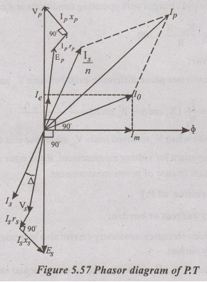
Transformation (voltage) ratio is given by
R = Vp /Vs = n+ nIs (Rs cos Δ + Xs sin Δ) + Ie rp + Imrp/Vs
Errors in P.T
Like C.T, P.T also introduce errors. This errors are of two types.
1. Ratio error (voltage):
Transformation ratio changes with operating conditions and causes this error.
% Ratio error = Kn - R × 100/R
2. Phase angle error:
In an actual transformer phase difference exist between Vp and Vs reversed.
Phase angle, Ɵ = Is/Vs (Xs cosΔ - Rs sin Δ) + Ie xp - Im rp/nVs
'Ɵ' is taken as +ve when Vs reversed leads Vp otherwise it is taken as -ve.
Ratio error is important for voltage measurement. Ratio error and phase angle error, both are important in case of power measurement.
Characteristics of P.T
1. Effect of secondary current or burden:
If secondary burden increases, secondary current also increases and this cause an increase in primary current.
For a given value of Vp, Vs decreases and hence the actual ratio increases as the VA increases.
Vp - Advanced in phase
Vs reversed - retarded in phase.
Ɵ increases as burden VA increases.
2. Effect of power factor of secondary burden:
If the power factor of secondary circuit burden is decreased, Δ is increased. This cause Ip to shift towards Io. Vp and Vs come more nearly into phase with Ep and Es. This makes an increase in Vp but Vp is constant and therefore Ep reduces relative to Vp.Vs reduces relative to Es. Ratio error increases as power factor of VA reduces.
Vp - retarded in phase
Vs reversed - advanced in phase.
Ɵ decreases as secondary VA powerfactor decreases (lagging).
3. Effect of frequency:
For constant voltage, flux α 1/ frequency and therefore voltage ratio decreases.
The change in ratio, because of change in frequency are dependent upon Io and leakage reactances.
Vp - Advanced in phase
Vs - reversed - retarded in phase.
Ɵ Increases with an increase in frequency.
4. Effect of primary voltage:
The supply voltage connected to the primary winding of the P.T does not change widely. Therefore change in ratio and phase angle errors are of no importance.
5.10.2.4 Methods to Reduce Errors
1. The value of Ie and Im is reduced by providing short magnetic path, Quality material used as core, low flux density in core and suitable precautions in the assembly and interleaving of core.
2. Leakage reactance is minimized by placing the two windings co-axial and close to each other. Less number of turns of windings also reduces leakage reactance in case of high flux density.
3. Resistance is minimized by providing low crossection of core and small length of mean turn in case of high flux density.
4. Turns compensation:
Turns ratio should be made less than nominal ratio. This can be done by increasing the number of secondary winding turns or by decreasing the number of primary winding turns.
Short Circuit Effect in the Secondary Winding of the P.T:
A short circuit of the secondary winding of the P.T causes serious damage to the transformer. So a fuse is used on the primary side to protect the power system. Another fuse is used on the secondary side to protect the P.T from faulty switching and faulty earthing.
Difference between C.T and P.T
Advantages of Instrument Transformer
1. Readings does not depends on circuit constants R,L,C and number of meters connected in the circuit.
2. Instrument transformer steps down the current and voltage to standard values like 5A, 1A and 110V. Therefore standard instruments are used for metering.
eg:- 1000A/5A-C.T
66KV/110V - P.T
3. Usage of standard instruments for metering reduces cost and its replacement is also easy.
4. Extension of range is possible.
5. Metering circuit is isolated from the high voltage / current power circuit.
6. Low power consumption in metering circuit.
7. Several instruments can be operated from a single instrument transformer.
8. Provides safety for the operating personnel.
Applications
1. Instrument transformers are used in the panel board of substation or grid station to measure the bus bar current.
2. I.T's are used in power measuring circuits. It is shown in the following diagram.
3. I.T's are used in substations and power houses.
4. I.T's are used along with relays in protection circuits.
Basic Electrical and Electronics Engineering: Unit V: Measurements and Instrumentation : Tag: : Construction, Operation Principle, Equivalent Circuit Diagram, Characteristics, Advantages, Applications - Instrument Transformers
Related Topics
Related Subjects

Basic Electrical and Electronics Engineering
BE3251 2nd semester Mechanical Dept | 2021 Regulation | 2nd Semester Mechanical Dept 2021 Regulation

Basic Electrical and Electronics Engineering
BE3251 2nd Semester CSE Dept 2021 | Regulation | 2nd Semester CSE Dept 2021 Regulation