Database Management System: Unit II: Databases Design
Examples based on ER Diagram
Databases Design - Database Management System
An E-R diagram can express the overall logical structure of a database graphically.
Examples based on ER Diagram
An E-R diagram can express the overall logical
structure of a database graphically.
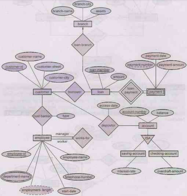
Example 2.5.1 Draw the ER diagram for banking systems (home
loan applications). AU: Dec.-17, Marks 8
OR Draw an ER diagram corresponding to customers
and loans. AU: May.-14, Marks 8
OR Write short notes on: E-R diagram for banking
system. AU: Dec.-14, Marks 8
Solution:
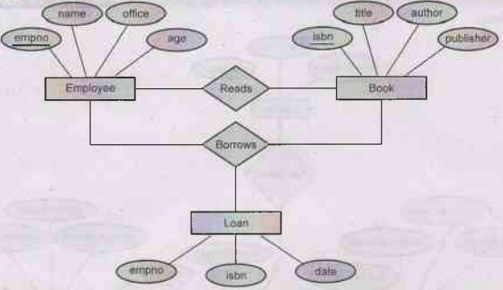
Example 2.5.2 Consider the relation schema given in Figure.
Design and draw an ER diagram that capture the information of this schema.AU: May-17, Marks 5
Employee(empno,name,office,age)
Books(isbn,title,authors,publisher)
Loan(empno,isbn,date)
Solution:
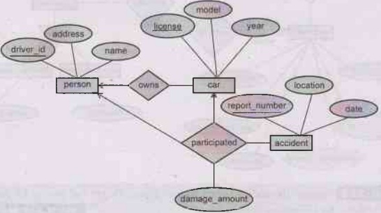
Example 2.5.3 Construct an E-R diagram for a car insurance
company whose customers own one or more cars each. Each car has associated with
it zero to any number of recorded accidents. Each insurance policy covers one
or more cars and has one or more premium payments associated with it. Each
payment is for particular period of time and has an associated due date and
date when the payment was received
AU: Dec.-16, Marks 7
Solution:
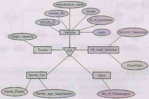
Example 2.5.4 A car rental company maintains a database for all
vehicles in its current fleet. For all vehicles, it includes the vehicle
identification number license number, manufacturer, model, date of purchase and
color. Special data are included for certain types of vehicles.
Trucks: Cargo capacity
Sports cars: horsepower, renter age requirement
Vans: number of passengers
Off-road vehicles: ground clearance, drivetrain
(four-or two-wheel drive)
Construct an ER model for the car rental company
database."AU: Dec.-15, Marks 16
Solution:
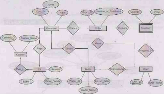
Example 2.5.5 Draw E-R diagram for the "Restaurant Menu
Ordering System", which will facilitate the food items ordering and
services within a restaurant. The entire restaurant scenario is detailed as
follows. The customer is able to view the food items menu, call the waiter,
place orders and obtain the final bill through the computer kept in their
table. The Waiters through their wireless tablet PC are able to initialize a
table for customers, control the table functions to assist customers, orders,
send orders to food preparation staff (chef) and finalize the customer's bill.
The Food preparation staffs (chefs), with their touch-display interfaces to the
system, are able to view orders sent to the kitchen by waiters. Duringpreparation
they are able to let the waiter know the status of each item, and can send
notifications when items are completed. The system should have full
accountability and logging facilities, and should support supervisor actions to
account for exceptional circumstances, such as a meal being refunded or walked
out on.
Solution:
Example 2.5.6 A university registrar's office maintains data
about the following entities:
(1) courses,
including number, title, credits, syllabus, and prerequisites;
(2) course offerings, including course number,
year, semester, section number,
instructor(s), timings, and classroom;
(3) students, including student-id, name, and
program; and
(4) instructors, including identification number,
name, department, and title.
Further, the enrollment of students in courses and
grades awarded to students in each course they are enrolled for must be
appropriately modeled. Construct an E-R diagram for the registrar's office.
Document all assumptions that you make about the mapping constraints.AU:
Dec.-13, Marks 10
Solution:

Example 2.5.7 What is aggregation in ER model? Develop an ER
diagram using aggregation that captures following information: Employees work
for projects. An employee working for particular project uses various
machinery. Assume necessary attributes. State any assumptions you make. Also
discuss about the ER diagram you have designed.
Solution Aggregation: Refer section 2.4.3.
ER Diagram: The ER diagram for above described scenario can be drawn as
follows-

The above ER model contains the redundant information, because every
Employee, Project, Machinery combination in works_on relationship is also
considered in manages relationship. To avoid this redundancy problem we can
make use of aggregation relationship in ER diagram as follows -

We can then create a binary relationship manages for between
Manager and (Employee, Project, Machinery).
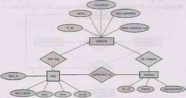
Example 2.5.8 Construct an E-R diagram for a hospital with a set
of patients and a set of medical doctors. Associate with each patient a log of
the various tests and examinations conducted. AU: Dec.-07, Marks 8
Solution:
Example 2.5.9 Consider the following information about a
university database:
i) Professors have an SSN, a name, an age, a rank and a
research specialty.
ii) Projects have a project number, a sponsor name,
(e.g. NSF), a starting date, an ending date and a budget.
iii) Graduate students have an SSN, a name, an age and a
degree program (e.g. M.S. or Ph.D.).
iv) Each project is managed by one professor (known as
the project's principal investigators)
v) Each project is worked on by one or more professors
(known as the project's co- investigators).
vi) Professors can manage and/or work on multiple
projects.
vii) Each project is worked on by one or more graduate
students (known as the project's research assistants).
viii) When graduate students work on a project, a
professor must supervise their work on the project. Graduate students can work
on multiple projects, in which case they will have a (potentially different)
supervisor for each one.
ix) Departments have a department number, a department
name and a main office.
x) Departments have a professor (known as the
chairman) who runs the department.
xi) Professors work in one or more departments and for
each department that they work in, a time percentage is associated with their
job,
xii) Graduate students have one major department in
which they are working on their degree.
xii) Each graduate student has another, more senior
graduate student (known as a student advisor) who advises him or her on what
courses to take.
xiii) Design and draw an ER diagram that captures the
information about the university.
Use only the basic ER model here; that is entities,
relationship and attributes.
Be sure to indicate any key and participation
constraints.
Solution:

Database Management System: Unit II: Databases Design : Tag: : Databases Design - Database Management System - Examples based on ER Diagram
Related Topics
Related Subjects
Database Management System
CS3492 4th Semester CSE Dept | 2021 Regulation | 4th Semester CSE Dept 2021 Regulation