Database Management System: Unit II: Databases Design
ER Diagrams
Databases Design - Database Management System
An E-R diagram can express the overall logical structure of a database graphically.E-R diagrams are used to model real-world objects like a person, a car, a company and the relation between these real-world objects.
ER Diagrams
An E-R diagram can express the overall logical structure of a database
graphically.E-R diagrams are used to model real-world objects like a person, a
car, a company and the relation between these real-world objects.
Features of ER model
i) E-R diagrams are used to represent E-R model in a database, which
makes them easy to be converted into relations (tables).
ii) E-R diagrams provide the purpose of real-world modeling
of objects which makes them intently useful.
iii) E-R diagrams require no technical knowledge and no
hardware support.
iv) These diagrams are very easy to understand and easy to create even
by a naive user.
v) It gives a standard solution of visualizing the data logically.
Various Components used in ER Model are-

Mapping Cardinality Representation using ER Diagram
There are four types of relationships that are considered for key
constraints.
i) One to one relation: When entity A is associated with at the most one entity B
then it shares one to one relation. For example - There is one project manager
who manages only one project.

ii) One to many :When
entity A is associated with more than one entities at a time then there is one
to many relation. For example - One customer places order at a time.

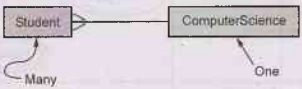
iii) Many to one : When
more than one entities are associated with only one entity then there is is
many to one relation. For example – Many student take a ComputerSciCourse

Alternate representation can be
iv) Many to many: When
more than one entities are associated with more than one entities. For example
-Many teachers can teach many students.

Alternate representation can be

Ternary Relationship
The relationship in which three entities are involved is
called ternary relationship. For example -

Binary and Ternary Relationships
• Although binary relationships seem
natural to most of us, in reality it is sometimes necessary to connect three or
more entities. If a relationship connects three entities, it is called ternary
or "3-ary."
• Ternary relationships are required
when binary relationships are not sufficient to accurately describe the
semantics of an association among three entities.
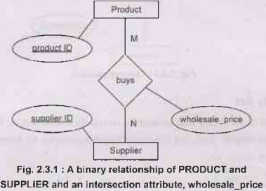
• For example - Suppose, you have a
database for a company that contains the entities, PRODUCT, SUPPLIER, and
CUSTOMER. The usual relationships might be PRODUCT/ SUPPLIER where the company
buys products from a supplier - a normal binary relationship. The intersection
attribute for PRODUCT/SUPPLIER is wholesale_price
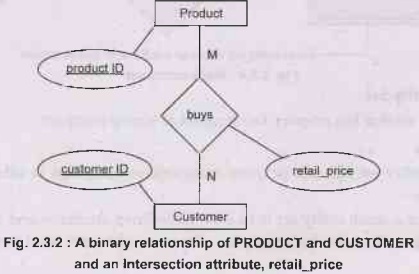
• Now consider the CUSTOMER entity,
and that the customer buys products. If all customers pay the same price for a
product, regardless of supplier, then you have a simple binary relationship
between CUSTOMER and PRODUCT. For the CUSTOMER/PRODUCT relationship, the
intersection attribute is retail_price.
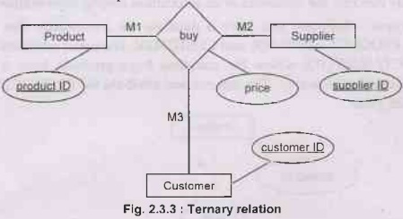
• Single ternary relation: Now consider a different scenario. Suppose the
customer buys products but the price depends not only on the product, but also
on the supplier. Suppose you needed a customerID, a productID, and a supplierID
to identify a price. Now you have an attribute that depends on three things and
hence you have a relationship between three entities (a ternary relationship)
that will have the intersection attribute, price.
Weak Entity Set
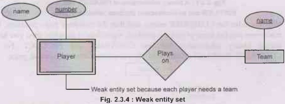
• A weak entity is an entity that cannot be uniquely
identified by its attributes alone. The entity set which does not have
sufficient attributes to form a primary key is called as weak entity set.
• Strong Entity Set
The entity set that has primary key is called as strong entity set
Weak entity set because each player needs a team
Weak entity rules
• A weak entity set has one or more many-one relationships
to other (supporting) entity sets.
• The key for a weak entity set is its own underlined
attributes and the keys for the supporting entity sets. For example -
player-number and team-name is a key for Players.
Difference between Strong and Weak Entity Set

Database Management System: Unit II: Databases Design : Tag: : Databases Design - Database Management System - ER Diagrams
Database Management System: Unit II: Databases Design
Under Subject
Database Management System
CS3492 4th Semester CSE Dept | 2021 Regulation | 4th Semester CSE Dept 2021 Regulation
Database Management Systems
CS25C13 4th Semester CSE, CSE(CY), IT, AIDS Departments | 2025 Regulation | 4th Semester 2025 Regulation
Related Subjects

Environmental Sciences and Sustainability
GE3451 ESS 4th Semester | 2021 Regulation | 4th Semester EEE Dept 2021 Regulation
Theory of Computation
CS3452 4th Semester CSE Dept | 2021 Regulation | 4th Semester CSE Dept 2021 Regulation
Artificial Intelligence and Machine Learning
CS3491 4th Semester CSE/ECE Dept | 2021 Regulation | 4th Semester CSE/ECE Dept 2021 Regulation
Database Management System
CS3492 4th Semester CSE Dept | 2021 Regulation | 4th Semester CSE Dept 2021 Regulation
Algorithms
CS3401 4th Semester CSE Dept | 2021 Regulation | 4th Semester CSE Dept 2021 Regulation
Introduction to Operating Systems
CS3451 4th Semester CSE Dept | 2021 Regulation | 4th Semester CSE Dept 2021 Regulation