Basic Electrical and Electronics Engineering: Unit IV: Digital Electronics
Adders
Operation, Circuit diagram, Logic Symbol, Truth Table, Equation | Digital Electronics
Digital computers and calculators consist of arithmetic and logic circuit. The basic building blocks of the arithmetic unit in a digital computer are adders.
ADDERS
Half Adder
Digital computers and calculators consist of arithmetic and logic circuit. The basic building blocks of the arithmetic unit in a digital computer are adders.
The simplest combinational circuit which performs the arithmetic addition of two binary digits is called a half-adder. It is shown figure 4.17, the half adder has two inputs and two outputs.
The two inputs are the two 1 - bit number A and B and the two outputs are the sum(s) of A and B and the carry bit denoted by C.

From table 4.26 the logic expression for the sum output can be written as a sum of product expression by summing up the input combinations for which the sum is equal to 1.
In the truth table 4.26, the sum output is 1 when AB = 01 and AB = 10. Therefore, the expression for sum is
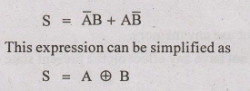
Similarly, the logic expression for carry output can be expressed as a sum of product expression by summing up the input combinations for which the carry is equal to 1. In the truth table, the carry is 1 when AB = 11 therefore,
C = AB
Full Adder
A half- adder has only two inputs and there is no provision to add a carry coming from the lower order bits when multi bit addition is performed. For this purpose, a dull-adder is designed.
A full-adder is a combinational circuit that performs the arithmetic sum of three input bits and produces a sum output and a carry.
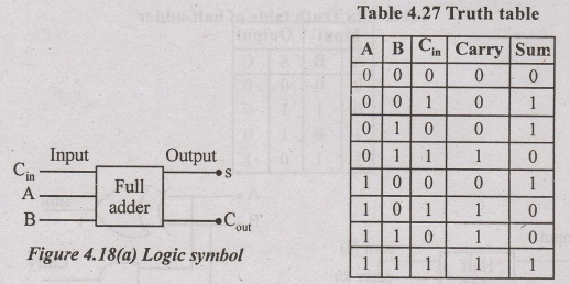
It consists of three inputs and two output. The two input variables denoted by A and B, the third input Cin, represents the carry from the previous lower significant position. The outputs are designated by the symbols S(sum) and Cout(carry).
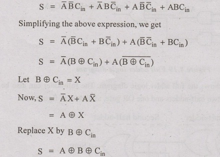
From the truth table 4.27, the logic expression for S can be written by summing up the input combinations for which the sum output is 1 as
Similarly, the logic expression for Cout can be written by summing up the input combinations for which C out is 1, as given below.


Figure 4.19 shows the full adder logic diagram. The full-adder can also be implemented with two half-adders and one OR gate, as shown in figure 4.20.

Basic Electrical and Electronics Engineering: Unit IV: Digital Electronics : Tag: : Operation, Circuit diagram, Logic Symbol, Truth Table, Equation | Digital Electronics - Adders
Related Topics
Related Subjects

Basic Electrical and Electronics Engineering
BE3251 2nd semester Mechanical Dept | 2021 Regulation | 2nd Semester Mechanical Dept 2021 Regulation

Basic Electrical and Electronics Engineering
BE3251 2nd Semester CSE Dept 2021 | Regulation | 2nd Semester CSE Dept 2021 Regulation