Digital Principles and Computer Organization: Unit II (a): Synchronous Sequential Logic
Various Representation of Flip-Flops
Synchronous Sequential Logic - Digital Principles and Computer Organization
Here, the 0 and the 1 in the circle represents the two states of the flip-flops and the arcs with arrow heads indicate the state transitions for specific inputs of the flip-flop.
Various Representation of
Flip-Flops
AU May-04,05,06,07,08,09,10,11,15,
Dec.-03,07,09,10, June-16
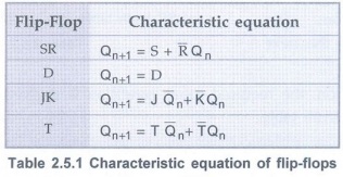
Characteristic Equations of Flip-Flops
• The characteristics equations for
various flip-flops are summarized in Table 2.5.1.
Flip-Flops as Finite State Machines
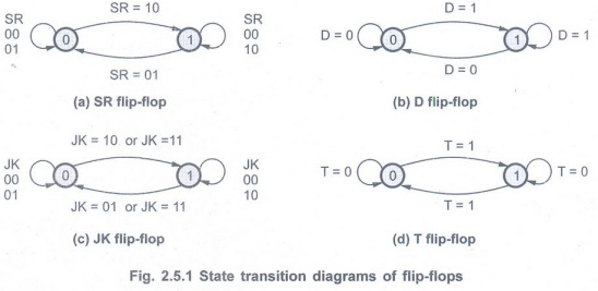
• Fig. 2.5.1 shows the state transition
diagram for all flip-flops. Here, the 0 and the 1 in the circle represents the
two states of the flip-flops and the arcs with arrow heads indicate the state
transitions for specific inputs of the flip-flop.
• For example, when SR flip-flop is in
state 0, it goes to state 1 if SR inputs are 10, i.e. S = 1 and R = 0.
Flip-Flop Excitation Table
• A truth table that lists the required
inputs conditions for a given change of state. Such a table is known as an
excitation table of the flip-flop.
SR Flip-Flop
• Table 2.5.2 (a) and (b)show the truth
table and excitation tables for SR flip-flop, respectively.
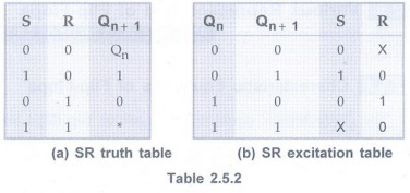
• There are four possible transitions from
the present state to the next state.
• For each transition, the required input
condition is derived from the information available in the truth table.
Note The symbol
"X" in the table represents a don't care condition, i.e., it
indicates
that to get required output it does not
matter whether the input is either 1 or 0.
• 0 → 0 Transition: The present
state of the flip-flop is 0 and is to remain 0 when a clock pulse is applied.
Looking at truth table of SR flip-flop we can understand that, this can happen
either when R = S = 0 (no-change condition) or when R = 1 and S = 0. Thus, S
has to be at 0, but R can be at either level. The table indicates this with a
"0" under S and an "X" (don't care) under R.
• 0 → 1 Transition:
The present state is 0 and is to change to 1. This can happen only when S = 1
and R = 0 (set condition). Therefore, S has to be 1 and R has to be 0 for this
transition to occur.
• 1→ 0 Transition:
The present state is 1 and is to change to a 0. This can happen only when S = 0
and R = 1 (reset condition). Therefore, S has to be 0 and R has to be 1 for
this transition to occur.
• 1 → 1 Transition:
The present state is 1 and is to remain 1. This can happen either when S = 1
and R = 0 (set condition) or when S = 0 and R = 0 (no change condition). Thus R
has to be 0, but S can be at either level. The table indicates this with a
"X" under S and "0" under R.
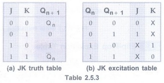
JK Flip-Flop
• The truth table and excitation table
for JK flip-flop are shown in Table 2.5.3 (a) and (b) respectively.
• 0→0 Transition: When both
present state and next state are 0, the J input must remain at and the K input
can be either 0 and 1.
• 0 → 1 Transition: The present
state is 0 and is to change to 1. This can happen either when J = 1 and K = 0
(set condition) or when J = K = 1 (toggle condition). Thus, J has to be 1, but
K can be at either level for this transition to occur.
• 1→0 Transition:
The present state is 1 and is to change to 0. This can happen either when J = 0
and K = 1 or when J = K = 1. Thus, K has to be 1 but J can be at either level.
• 1→ 1 Transition:
When both present state and next are 1, the K input must remain at 0 while the
J input can be 0 or 1.
• The excitation table for JK flip-flop
has more don't care conditions than the excitation table for RS flip-flop.
• The don't care terms usually simplify
the function. Therefore, the combinational circuits using JK flip-flops for the
input functions are likely to be simpler than those using RS flip-flops.
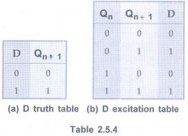
D Flip-Flop
• The Table 2.5.4 (a) and (b) show the
truth table and excitation table for
D flip-flop, respectively.
• In D flip-flop, the next state is
always equal to the D input and it is independent of the present state.
Therefore, D must be 0 if Qn+1 has to be 0, and 1 if Qn+1
has to be 1, regardless of the value of Qn.
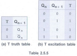
T Flip-Flop
• The Table 2.5.5 (a) and (b) show the
truth table and the excitation table for T flip-flop, respectively.
• When input T = 1, the state of the
flip-flop is complemented; when T = 0, the state of the flip-flop remains
unchanged. Therefore, for 0 → 0 and 1 → 1 transitions T must be 0 and for 0 → 1
and 1 → 0 transitions T must be 1.
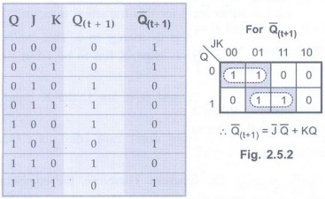
Example 2.5.1
Show that the characteristic equation of Qʹ(t+1) of JK flip-flop is
Qʹ(t+1)= J'Q' + KQ AU Dec.-07, Marks 4
Solution:
From Fig. 2.5.2 we can write truth table for JK flip flop as shown below.
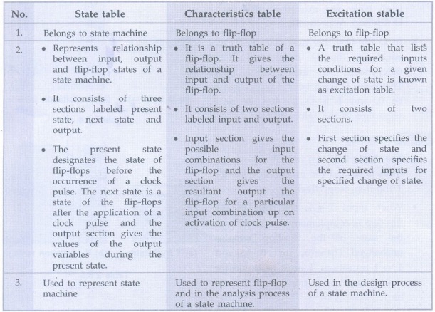
Example 2.5.2 Explain
the difference between a state table, characteristics table and an excitation
table. AU: May-15, Marks 6
Solution :
Review Questions
1. Give the characteristic equation and state diagram of JK flip-flop. AU: May-04, 10, 11, Dec.-09, Marks 2
2. Give the excitation table for JK flip-flop. AU: May-05, 06, 09, Dec.-10, June-16 Marks 2
3. Obtain the excitation table of D
flip-flop. AU May-06, Dec.-10, Mark 1
4. Give the state diagram of JK
flip-flop. AU May-07, Marks 2
5. What is excitation table? AU
May-08, Marks 2
6. Give state diagram of JK flip-flop. AU
May-10, Marks 2
7. Draw state diagram of SR flip-flop. AU:
Dec.-10, Marks 2
8. Draw the truth table and excitation
table of T flip-flop. AU: Dec.-10, Marks 2
9. State the characteristics equations
of various flip-flops.
Digital Principles and Computer Organization: Unit II (a): Synchronous Sequential Logic : Tag: : Synchronous Sequential Logic - Digital Principles and Computer Organization - Various Representation of Flip-Flops
Related Topics
Related Subjects

Digital Principles and Computer Organization
CS3351 3rd Semester CSE Dept | 2021 Regulation | 3rd Semester CSE Dept 2021 Regulation