Digital Principles and Computer Organization: Unit II (b): Analysis & Design of Clocked Sequential Circuits
Two marks Questions with Answers
Analysis & Design of Clocked Sequential Circuits - Digital Principles and Computer Organization
The information stored in the memory elements at any given time defines the state at that time of the corresponding sequential circuit.
Two Marks Questions with
Answers
Q.1 Give the comparison between synchronous and asynchronous sequential circuits.
(Refer section 3.1) AU: Dec.-10

Q.2 Define a state. AU: Dec.-06, May-09
Ans. : The information
stored in the memory elements at any given time defines the state at that time
of the corresponding sequential circuit.
Q.3 What are the classification of
sequential circuits ?
Ans. : The sequential
circuits are classified on the basis of timing of their signals into two types.
They are,
1. Synchronous sequential circuit.
2. Asynchronous sequential circuit.
Q.4 What do you mean by present state ?
Ans. : The information
stored in the memory elements at any given time defines the present state of
the sequential circuit.
Q.5 What do you mean by next state?
Ans. : The present
state and the external inputs determine the outputs and the next state of the sequential
circuit.
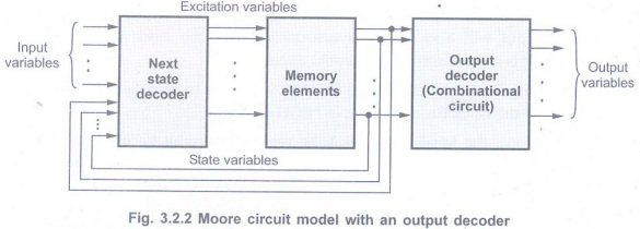
Q.6 Draw the block diagram of Moore model.
(Refer section 3.2.1) AU : May-10
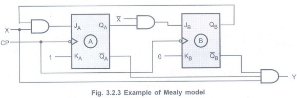
Q.7 What is a Mealy machine? Give an example.
(Refer section 3.2.2) AU: Dec.-08, May-13
• When the output of the sequential circuit depends on both the present state of flip-flop(s) and on the input(s), the sequential circuit is referred to as Mealy model.
• The output of the circuit is derived from the combination of present state of flip-flops and input(s) of the circuit.
• we can easily realize that, changes in the input within the clock pulses can not affect the state of the flip-flop. However, they can affect the output of the circuit.
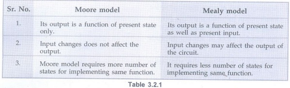
Q.8 Compare Moore and Mealy models.
(Refer section 3.2.3) AU: May-05, 09, Dec.-08, 10
Q.9 Define state table. AU: Dec.18
Ans. : For the design
of sequential counters we have to relate present states and next states. The
table which represents the relationship between present states and next states
is called state table.
Q.10 What are state diagrams and state
tables ? AU:
May-06
Ans. :State diagram is
a pictorial representation of a behaviour of a sequential circuit. The state is
represented by the circle, and the transition between states for different
input conditions are indicated by directed lines connecting the circles.
State table is the translation of state
diagram into a tabular form; representing relationships among input, output and
flip-flop states.
Q.11 Explain about state reduction or Why is state reduction necessary? AU Dec.-04, 06; May-09
Ans. : The state
reduction is a technique that reduces the number of states in the sequential
circuit by keeping only one state for two or more redundant/equivalent states.
This reduces the number of required flip-flops and logic gates, reducing the
cost of the final circuit. Two states are said to be redundant or equivalent,
if every possible set of inputs generate exactly same output and same next
state.
Q.12 What is lockout? How it is
avoided? AU: Dec.-09, June-16
Ans. :In a counter, if
the next state of some unused state is again some unused state, it may happen
that the counter remains in unused states never to arrive at a used state. Such
a condition is called a lockout condition.
To avoid lockout, the counter should be
provided with an additional logic circuitry which will force the counter from
an unused state to the next state as initial
state.
Q.13 What is a self starting counter ? AU :
May-10
Ans. : In a counter if
the next state of some unused state is again an unused state and if by chance
the counter happens to find itself in the unused states and never arrived at a
used state then the counter is said to be in the lockout conditions. The
counter which never goes in lockout condition is called self starting counter.
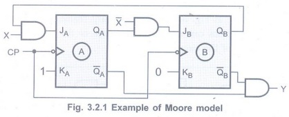
Q.14 What is Moore machine ?
(Refer section 3.2.1) AU: Dec.-07
• When the output of the sequential circuit depends only on the present state of the flip-flop,the sequential circuit is referred to as Moore model.
Q.15 Define state assignment. AU: Dec.-05
Ans. : The state
assignment is an one step in the design of sequential circuits which assigns
binary values to the states in such a way that it reduces the cost of the
combinational circuit that drives the flip-flops.
Q.16 Compare the ASM chart with a
conventional flow chart. AU Dec.-12
Ans. : The ASM chart
resembles a conventional flow chart, but is interpreted somewhat differently. A
conventional flow chart describes the sequence of procedural steps and decision
paths for an algorithm without concern for their time relationship. An ASM
chart describes the sequence of events as well as the timing relationship
between the states of a sequential controller and the events that occur while
going from one state to the next.
Q.17 What are the basic building blocks
of an algorithmic state machine chart? AU: May-11
Ans. :The basic
building blocks of an ASM chart are:
• State box
• Decision box and
• Conditional box
Q.18 Under what circumstances asynchronous circuits are preferred ? AU: Dec.-11
Ans. :Asynchronous
circuits can operate faster than synchronous circuits and hence they are
preferred when speed is an important criteria.
Q.19 When is a counter said to suffer from lockout?
(Refer section 3.4.7) AU: Dec.-02, 03
• In a counter if the next state of some unused state is again an unused state and if by chance the counter happens to find itself in the unused states and never arrived at an used state then the counter is said to be in the lockout conditions.

• The counter which never goes in lockout condition is called self starting counter.
Q.20 What are the models used to represent clocked sequential circuits ?
(Refer section 3.2)AU:
Dec.-06
The synchronous or clocked sequential circuits are represented by two models.
• Moore model: The output depends only on the present state of the flip-flops.
• Mealy model: The output depends on both the present state of the flip-flop(s) and on the input(s).
Q.21 A reduced state table has 14 rows.
What is the minimum number of flip-flops needed to build the sequential circuit
? AU: Dec.-04
Ans. :24> 14. Therefore, 4
flip-flops.
Q.22 Distinguish Moore and Mealy circuit.
(Refer section 3.2.3) AU: Dec.-14
Digital Principles and Computer Organization: Unit II (b): Analysis & Design of Clocked Sequential Circuits : Tag: : Analysis & Design of Clocked Sequential Circuits - Digital Principles and Computer Organization - Two marks Questions with Answers
Related Topics
Related Subjects

Digital Principles and Computer Organization
CS3351 3rd Semester CSE Dept | 2021 Regulation | 3rd Semester CSE Dept 2021 Regulation