Introduction to Operating Systems: Unit II(b): Deadlock
System Model
Deadlock - Introduction to Operating Systems
A lack of process synchronization can result in two extreme conditions are deadlock or starvation. Deadlock is the problem of multiprogrammed system.
UNIT II: Process Management
Chapter 3: Deadlock
Syllabus
Deadlock
- Methods for handling deadlocks, Deadlock prevention, Deadlock avoidance,
Deadlock detection, Recovery from deadlock.
System
Model
• A lack of process synchronization can result in two extreme conditions are deadlock or starvation. Deadlock is the problem of multiprogrammed system.
• Deadlock can be defined as the permanent
blocking of a set of processes that either complete for system resources. Deadlock is more serious than starvation.
•
Deadlock can occur on sharable resources such as files, printers, database,
disks, tape drives, memory, CPU cycles etc.
• A process is in deadlock state if it
was waiting for a particular event that will not occur. In a system deadlock,
one or more processes are deadlocked.
Deadlock
Example
Computer system is collection of
limited/finite number of resources. These resources are distributed among a
number of competing processes.
Resources
are of two types:
1. Reusable resources
2. Consumable resources.
• Reusable resource is used only by one
process at a time. Process can release resource after use. Processors, I/O channel,
I/O device, files, database, primary and secondary memory, semaphore are
example of the reusable resource.
• Consumable resource is one that can be
created and destroyed. There is no limit on the number of consumable resources
of a particular type.
• An interrupt, messages, signals and
messages in I/O buffers are examples of consumable resources.
• Process utilize the resources in the
following sequence:
1. Request for resource.
2.
Use of resource
3. Resource release.
• Process uses system call for requesting
the resource. After allocating resource to the process, it use or operate the
resource.
• The process releases the resource
after use.
• If
the resource is not available when it is requested, the requesting process is
forced to wait.
• Fig. 3.1.1 shows the deadlock with 4
process.
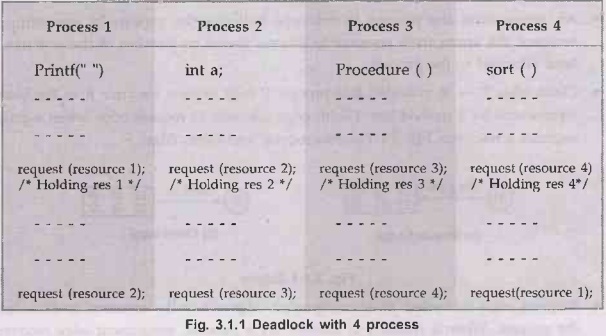
• Process 1 is holding resource 1 and
requesting resource 2; process 2 is holding resource 2 and requesting resource
3; process 3 is holding resource 3 and requesting resource 4. Process 1 is
holding resource 4 also.
•
Here deadlock occurs because none of the processes can proceed because all are
waiting for a resource held by another blocked process.
• To break this situation, one of the
process release the resource.
• Operating system must be handle the
deadlock situation. OS detect the deadlock and solve the deadlock problem.
Resource Allocation Graphs
• Resource
allocation graph is introduced by Holt. It is a directed graph that depicts a
state of the system of resources and processes.
• Process and resource are represented by node in directed graph. Graph consists of a set of vertices (V) and set of edges (E).
•
A process node is graphically represented by circle and shown in Fig. 3.1.2
•
A resource node is graphically represented by a rectangle and represents one
type of resources. Fig. 3.1.3 shows resources node.

•
The number of bullet symbols in a resource node indicates how many units of
that resource class exist in the system.
• An arrow from the process to
resource indicates the process is requesting the resource. An arrow from
resource to process shows an instance of the resource has been allocated to the
process.
• Claim edge
P→ R indicated, that process P may request resource R in the future;
represented by a dashed line. Claim edge converts to request edge when a
process requests a resource. Fig. 3.1.4 shows request and claim edge.
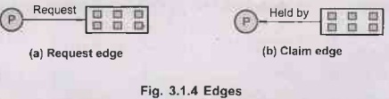
•
Request edge converted to an assignment edge when the resource is allocated to
the process. When a resource is released by a process, assignment edge
reconverts to a claim edge.
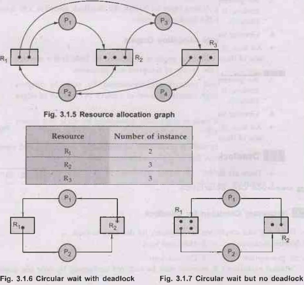
• Fig. 3.1.5 shows a resource allocation graph. System consists of process and resource P1, P2 and resource R1, R2
• Fig. 3.1.8 shows a resource allocation
graph. System consists of four processes (P1, P2, P3,
P4) and four resources (R1, R2, R3,
R4)

•
Resource managers and other operating system processes can be involved in a
deadlock. Deadlock is a global condition rather than a local one.
• An individual program cannot generally detect
a deadlock. It is blocked and unable to use the processor to do any work.
Deadlock detection must be handled by the operating system.
Introduction to Operating Systems: Unit II(b): Deadlock : Tag: : Deadlock - Introduction to Operating Systems - System Model
Related Topics
Related Subjects
Introduction to Operating Systems
CS3451 4th Semester CSE Dept | 2021 Regulation | 4th Semester CSE Dept 2021 Regulation