Basic Electrical and Electronics Engineering: Unit IV: Digital Electronics
Sub-Tractor
Operation, Circuit diagram, Logic Symbol, Truth Table, Equation | Digital Electronics
The half-subtractor is a combinational circuit which is used to perform subtraction of two input (A & B) and two outputs (D & Bout).
SUB-TRACTOR
Half Subtractor
The
half-subtractor is a combinational circuit which is used to perform subtraction
of two input (A & B) and two outputs (D & Bout). The logic
symbol for a half-subtractor is show in figure 4.21 (a). The truth for
half-subtractor is shown in table from the truth table it is clear that the
difference output is 0 if A = B and 1 if A≠B, the borrow output Bout
is 1 whenever A < B. If A is less than B, then subtraction is done by
borrowing 1 from the next higher order bit.

From
table, the Boolean expression for difference D and Barrow out Bout be
written as follows
From
the above equation, the half-subtractor can be implemented using an EX - OR
gate, a NOT gate and AND gate as shown in figure 4.21(b).
Full-Subtractor
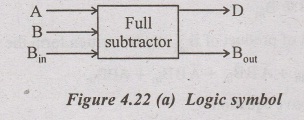
A
full-subtractor is a combinational circuit that performs subtraction involving
three bits inputs (A, B, B.) and two outputs (D and Bout). The truth
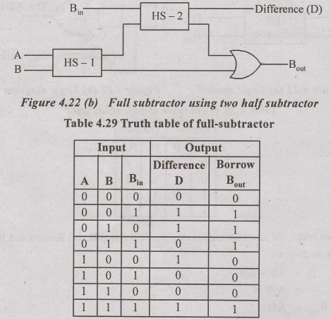
table for the full-subtractor is given in table 4.29. The full-subtractor can
be implemented using two half-subtractors and an OR gate as shown in figure
4.22.
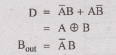
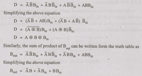
From
the table the sum of product expression for the difference (D) output can be
written as
Basic Electrical and Electronics Engineering: Unit IV: Digital Electronics : Tag: : Operation, Circuit diagram, Logic Symbol, Truth Table, Equation | Digital Electronics - Sub-Tractor
Related Topics
Related Subjects

Basic Electrical and Electronics Engineering
BE3251 2nd semester Mechanical Dept | 2021 Regulation | 2nd Semester Mechanical Dept 2021 Regulation

Basic Electrical and Electronics Engineering
BE3251 2nd Semester CSE Dept 2021 | Regulation | 2nd Semester CSE Dept 2021 Regulation