Introduction to Operating Systems: Unit IV(a): Storage Management
Mass Storage System
Storage Management - Introduction to Operating Systems
A storage device is any device used in a computer to store information. It will retain this information when the computer is switched off.
UNIT IV: Storage Management
Chapter 5: Storage Management
Syllabus
Mass
Storage system - Disk Structure - Disk Scheduling and Management; I/O Systems -
I/O Hardware, Application I/O interface, Kernel I/O subsystem.
Mass Storage System
• A storage device is any device used in
a computer to store information. It will retain this information when the
computer is switched off.
• Type of storage device used varies
based on the type of data and the rate at which it is created and used.
• Examples of storage devices are hard
disk, CD-ROM, magnetic tape and removable media etc.
• The computer has many types of data storage
devices. Some of them can be classified as the removable data storage devices
and the others as the non removable data storage devices.
1.
Hard disk: The most common form of internal storage device
used in a computer is a hard disk. A hard disk has a circular, magnetized
surface on which the data is stored. A hard disk spins at a speed of between 60
and 120 revolutions per second. The data stored on the hard disk is read or
written by a head that floats just above the disk (less than 0.1 mm) on a
cushion of air. The surface of a hard disk is divided up into sectors and
tracks. Data is stored in the 'blocks' created by the sectors and tracks.
Moving data into a 'block' is called random access.
2.
Compact disk: Compact disks can be used to store much
more data than aahe floppy disk. Most compact disks can hold 650 megabytes of
data. There are three main types of compact disk: CD-ROM, CD-R, CD-RW.
3.
Magnetic tape: This is a cheap method of storing large
amounts of data (typically 26 gigabytes) and is often used as a 'backing store'
for large and mainframe computers.
4. Removable media: Zip drives are similar to floppy
drives and use special (and rather expensive) floppy disks that can hold
between 100 megabytes and 2 gigabytes of data.
Characteristics of Storage Device
1. When power to the device is shut off,
data stored on the medium remains.
2.
Storage devices are cheaper than memory.
3. They are capable of storing more
data.
4. Rotational speeds have increased over
time.
5. Storage devices are used for backup.
Magnetic Disk
• To store computer data, hard disks,
flash memory, magnetic tape and optical Wiedsmil
•
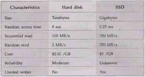
Alternate storage for hard disk is Solid State Disks (SSD). These flash memory
tollon based devices offer a different set of tradeoffs from a standard disk.
At the same time, capacity of the hard disk also increases.
•
Hybrid
category is introduced for storage media. It is hard disks with large flash
memory buffers. Disk sizes are specified in gigabytes.
•
Performances of hard disk and SSD technology is given below:
•
Hard disk contains several rotating platters coated with magnetic film. They
are read and written by tiny skating heads that are mounted on a metal arm that
swings back and forth to position them. Heads float close to the surface of the
platters but do not actually touch.
• A hard disk is really a set of stacked
"disks," each of which, like phonograph records, has data recorded
electromagnetically in concentric circles or "tracks" on the disk.
• A "head" writes or reads the
information on the tracks. Two heads, one on each side of a disk, read or write
the data as the disk spins. Each read or write operation requires that data be
located, which is an operation called a "seek."
• A hard disk/drive unit comes with a
set rotation speed varying from 4500 to 7200 rpm. Disk access time is measured
in milliseconds.
•
Although the physical location can be identified with cylinder, track and
sector locations, these are actually mapped to a Logical Block Address (LBA)
that works with the larger address range on today's hard disks.
•
Mean Time Between Failures (MTBF) is the predicted elapsed time between inherent failures of a system during operation. MTBF can be calculated as
the arithmetic mean (average) time between failures of a system.
•
Each disk drive is managed by a controller. Each type of controller can support
a fixed number of drives. SCSI
controllers support up to seven disks per controller or up to 15 disks per
controller.
• Each disk is assigned a drive address. This address is set
by a switch, a dial or jumpers on the disk or by the physical location of the
disk. Some SCSI devices, such as RAID's, have an additional identifying number
called a logical unit number. It is used to address disks within the device.
• Fig. 5.1.1 shows physical disk.
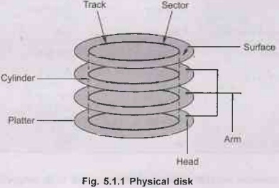
•
A disk consists of circular plates called platters. Each platter has an upper
and lower oxide-coated surface. Recording heads, at least one per surface, are
mounted on arms that can be moved to various radial distances from the center
of the platters. The heads float very close to the surfaces of the platters,
never actually touching them, and read and record data as the platters spin
around.
•
A ring on one surface is called a track. Each track is divided into disk
blocks. Sometimes called sectors, these physical blocks on a disk are different
from file system blocks.
•
Formatting a disk divides the disk into tracks and disk blocks that can be
addressed by the disk controller, writes timing marks, and identifies bad areas
on the disk.
• SCSI disk drives are shipped
preformatted. They do not require formatting at any time. Bad block handling is
performed automatically by SCSI disks. Bad blocks are areas of a disk that
cannot reliably store data.
Platter
• Platter is a circular, metal disk that
is mounted inside a hard disk drive. Several platters are mounted on a fixed
spindle motor to create more data storage surfaces in a smaller area.
• The platter has a core made up of
aluminum or glass substrate, covered with a thin layer of Ferric oxide or
cobalt alloy. On both sides of the substrate material, a thin coating is
deposited by a special manufacturing technique. This, thin coating where
actual data is stored is the media layer.
•
Attributes of platter
1. It is a rigid, round disk this is
coated with magnetically sensitive material.
2. Data is stored in binary code.
3.
It is encoded by polarizing magnetic areas on the disk surface.
4.
Data can be written to and read from both surfaces of a platter.
5. A platter's storage capacity varies
across drives.
Tracks
• Each platter is broken into thousands
of tightly packed concentric circles, known as tracks. These tracks resemble
the structure of annual rings of a tree.
• All the information stored on the hard
disk is recorded in tracks. Starting from zero at the outer side of the
platter, the number of tracks goes on increasing to the inner side.
• Each track can hold a large amount of
data counting to thousands of bytes.
Sectors
• Each track is further broken down into
smaller units called sectors. As sector is the basic unit of data storage on a
hard disk. Disk contains concentric tracks. Tracks are divided into sectors. A
sector is the smallest addressable unit in a disk.
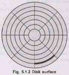
•
Fig.
5.1.2 shows surface of disk showing tracks and sectors.
• A single track typically can have
thousands of sectors and each sector can hold more than 512 bytes of data. A
few additional bytes are required for control structures and error detection
and correction.
Clusters:
Sectors are often grouped together
to form clusters.
Read/Write
Heads
•
The
heads are an interface between the magnetic media where the data is stored and
electronic components in the hard disk. The heads convert the information,
which is in the form of bits to magnetic pulses when it is to be stored on the
platter and reverses the process while reading.
• The heads are the most sophisticated
part of the hard disk. Each platter has two read/write heads, one mounted on
the top and the other one at the bottom. These heads are mounted on head
sliders, which are suspended at the ends of head
•
The head arms are all fused into a singular structure called actuator, which is
responsible for their movement. Drives rotate at 60 to 200 times per second.
•
Transfer rate is rate at
which data flow between drive and computer.
Positioning
time (random-access time) is time to move disk arm to desired cylinder
(seek time) and time for desired sector to rotate under the disk head. Head
crash results from disk head making contact with the disk surface.
• "Each platter (disc-shaped) is coated with magnetic
material on both surfaces. All platter surfaces has arm extended from fixed
position. Tip of the arm contains read/write head for reading or writing data.
• The arm moves the heads from the
spindle edge to the edge of the disc.
• When a program reads a byte from the
disk, the operating system locates the surface, track and sector containing
that byte, and reads the entire sector into a special area in main memory
called buffer.
•
The bottleneck of a disk access is moving the read/write arm.
• A cylinder is the set of tracks at a
given radius of a disk pack. A cylinder is the set of tracks that can be
accessed without moving the disk arm. All the information on a cylinder can be
accessed without moving the read/write arm.
Fig. 5.1.3 shows moving-head disk
mechanism.

•
The arm assembly is moved in or out to position a head on a desired track.
Tracks under heads make a cylinder. Only one head reads/writes at any one time.
Block size is a multiple of sector size.
•
Disks can be removable. Drive attached to computer via I/O bus. Buses vary,
including EIDE, ATA, SATA, USB, Fibre channel, SCSI etc.
•
Host controller in computer uses bus to talk to disk controller built into
drive or storage array.
•
Disk controllers typically embedded in the disk drive, which acts as an
interface between the CPU and the disk hardware. The controller has an internal
cache that it uses to buffer data for read/write requests.
Zone
Bit Recording
• Also known as multiple zone recording
or zone-CAV recording. Disk divided into zones. Fig. 5.1.4 shows zone bit
recording.
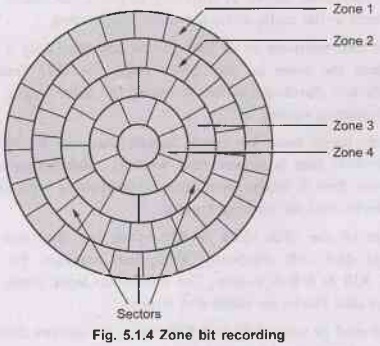
• Cylinders
in different zones have a different number of sectors. Number of sectors in a
particular zone is constant. Data is buffered so the data rate to the I/O
interface is constant.
•
Zoned-bit recording uses the disk more efficiently. It groups tracks into zones
that are based upon their distance from the center of the disk.
• Each
zone is assigned an appropriate number of sectors per track. This means that a zone near the center of the
platter has fewer sectors per track than a zone on the outer edge.
Solid State Disks
• SSD
is a storage device that is based on semiconductors rather than rotating
magnetic platters. Most SSDs are based on NAND Flash chips because they are
fast, highly reliable, widely available and are non-volatile, meaning they save
data even without a power source.
• SSDs use the same Serial ATA (SATA) or
IDE interface as hard drives, making them functionally identical.
•
Solid-state storage technology typically provides faster system performance
than traditional magnetic media drives. In addition, there are no moving parts
in SSDs and therefore the risk of mechanical failure is near zero. Solid-state
drives also provide improved overall system responsiveness while consuming much
less power than a traditional hard disk drive.
• A flash-based SSD typically uses a small amount of DRAM as a
cache, similar to the cache in hard disk drives. A directory of block placement
and wear leveling data is also kept in the cache while the drive is operating.
•
Each page of flash memory in an SSD can be rewritten only a limited number of
times. To limit the wear on any given page, the SSD firmware maintains a
mapping table and distributes writes across all the drive' pages. This
remapping is invisible to operating system.
•
Flash memory pages must be erased before they can be rewritten. Erasing is
separate operation that is slower than writing. Rebuilding a buffer of erased
pages is harder than it might seem because filesystems typically do not mark or
erase data blocks they are no longer using.
• Standard size of the disk block is
512 bytes, but that size is too small for filesystems to deal with efficiently.
Filesystem manages the disk in terms of clusters of 1 KiB to 8 KiB in size. The
translation layer maps filesystem clusters into ranges of disk blocks for reads
and writes.
• SSD only can read or write data in 4
KiB pages, file system cluster boundaries and SSD page boundaries should
coincide.
• Solid state disks (SSDs) mirror the
functionality of the existing standard of hard disk drives. SSD is volatile or
non-volatile depending upon memory technology.
• Because SSDs do not have moving parts
and therefore performance is insensitive to issues such as seek time and
rotational latency. Therefore, a simple FCFS policy will suffice.
• Solid state disks commonly use the
FCFS disk scheduling policy.
• SSDs have the advantage of being
faster than magnetic disks as there are no moving parts and therefore do not
have seek time or rotational latency.
• In
an SSD the LBAs are actually inside of the flash media. SSDs contain a number
of NAND flash components.
•
Solid-State Disks(SSDs) features :
1. Low power consumption.
2. Faster random access.
3.
Greater shock resistance.
•
SSD performance is being increased due to the exploitation of parallel I/O
architectures. An SSD interacts with the host computer via standard interface
such as PATA or SATA and behaves much like a standard hard drive.
• Operating systems use storage devices
to provide file systems and virtual memory. SSD controller is used to translate
read/write requests into flash memory operations.
•
The controller exploits RAM to temporarily buffer write requests or accessed
data during handling read/write requests.
• To increase the read/write bandwidth
of SSD, many SSDs use an interleaving technique that exploits the parallelism
of accessing multiple NAND chips simultaneously.
• If there are multiple independent
channels, the read/write bandwidth of SSDs can not be accelerated further by
exploiting inter-channel and intra-channel parallelism.
• SSD challenges:
1.
Reliability for large scale flash storage.
2. The balance between cost, performance
and lifetime.
3.
Cost per bit of NAND flash memory is still high.
Magnetic Tape
• Magnetic tapes are used mostly for
storing files of data: For example, a company's payroll record.
• Access is sequential and consists of
records that can be accessed one after other as Saib the tape moves along a
stationary read-write mechanism.
• It is one of the cheapest and slowest methods for storage
and has the advantage that tapes can be recovered when not in use.
• A magnetically coated strip of plastic
on which data can be encoded. Tape is much less expensive than other storage
mediums but commonly a much slower solution that is commonly used for backup.
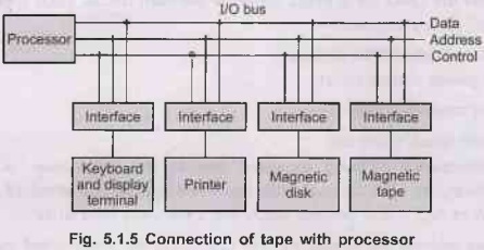
Fig.
5.1.5 shows connection of tape with processor.
• In addition, random access to magnetic
tape is about a thousand times slower than random access to magnetic disk, so
tapes are not very useful for secondary is storage.
•
The I/O bus consists of data lines, address lines, and control lines. Each
peripheral device has associated with it an interface unit. Each interface
decodes the address and control received from the I/O bus, interprets them for
the peripheral, and provides signals for the peripheral controller.
• The I/O bus from the processor is
attached to all peripheral interfaces. To communicate with a particular device,
the processor places a device address on the address lines. Each interface
attached to the I/O bus contains an address decoder that monitors the address
lines.
• When
the interface detects its own address, it activates the path between the bus
lines and the device that it controls.
• All peripherals whose address does not
correspond to the address in the bus are disabled their interface. At the same
time that the address is made available in the address lines, the processor
provides a function code in the control lines.
• The interface selected responds to the function code and
proceeds to execute it. The function code is referred to as an I/O command and
is in essence an instruction that is executed in the interface and its attached
peripheral unit.
• The interpretation of the command
depends on the peripheral that the processor is addressing. There are four
types of commands that an interface may receive. They are classified as
control, status, status, data output, and data input.
University
Question
1. Explain
the steps involved to transfer the stored historical information in a magnetic
tapes to the CPU for further processing through various storage devices. AU May-19, Marks 5
Introduction to Operating Systems: Unit IV(a): Storage Management : Tag: : Storage Management - Introduction to Operating Systems - Mass Storage System
Related Topics
Related Subjects
Introduction to Operating Systems
CS3451 4th Semester CSE Dept | 2021 Regulation | 4th Semester CSE Dept 2021 Regulation