Digital Principles and Computer Organization: Unit I: Combinational Logic
Magnitude Comparator
Combinational Logic - Digital Principles and Computer Organization
A comparator is a special combinational circuit designed primarily to compare the relative magnitude of two binary numbers.
Magnitude Comparator
AU:
Dec.-14, May-07,08,11,19
A comparator is a special combinational
circuit designed primarily to compare the relative magnitude of two binary
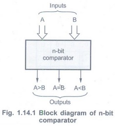
numbers. Fig. 1.14.1 shows the block diagram of an n-bit comparator. It
receives two n-bit numbers A and B as inputs and the outputs are AB, A = B and
A < B. Depending upon the relative magnitudes of the two number, one of the
outputs will be high.
Example 1.14.1
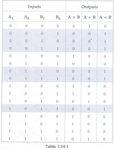
Design 2-bit comparator using gates. AU Dec.-14, Marks 8
Solution:
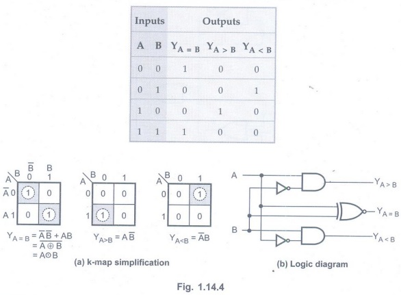
The truth table for 2-bit is given in Table 1.14.1.
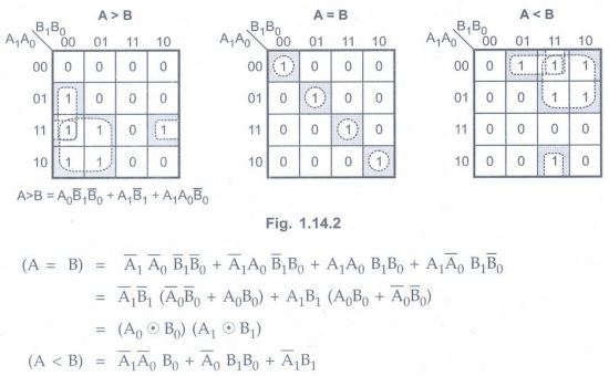
K-map simplification
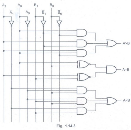
Logic diagram
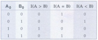
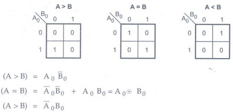
Example 1.14.2 Design a 1-bit comparator using basic gates. AU May-11, Marks 2
Solution:
Consider two one bit number A and B. The truth table is as shown.
4-bit Magnitude Comparator
Consider two binary numbers, A and B
with four digits each.
A = A3, A2, A1, A0
and B = B3, B2, B1, B0
When the numbers are binary, the digits
are either 0 or 1, and the equality of each pair of bits can be expressed
logically with an exclusive-NOR function as
xi = Ai Bi +
for i = 0, 1, 2, 3
where xi = 1 only if the pair of bits in position i are equal. This can be expressed as
(A = B) = x3, x2, x1, x0
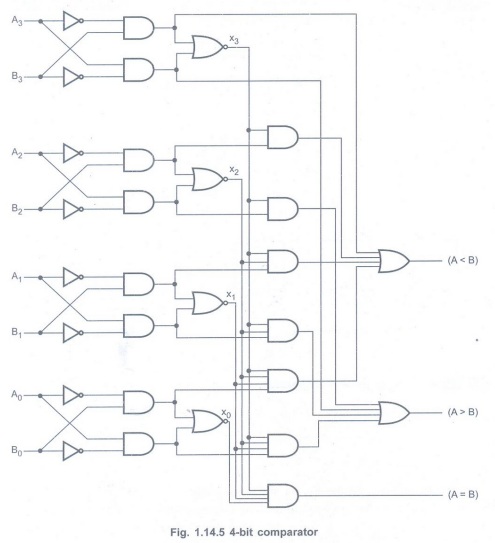
To determine whether A is greater or
less than B, we check the relative magnitudes of pairs of significant digits,
starting from the most significant position. If the two digits of a pair are
equal, we compare the next lower significant pair of digits. The comparison
continues until a pair of unequal digits is reached. If corresponding digit of
A is 0 and that of B is 1, we can say that A < B. If the corresponding digit
of A is 1 and that of B is 0, we can say that A > B.
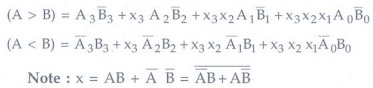
The above sequential comparison can be
expressed logically by the two Boolean functions.
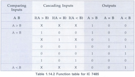
IC 7485 (4-bit Comparator)
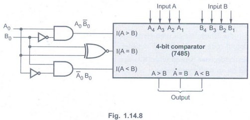
IC 7485 is a 4-bit comparator. It can be used to compare two 4-bit binary words by grounding I (A < B), and I (A > B), and connector input I (A = B) to Vcc. These ICs, can be cascaded to compare words of almost any length. Its 4-bit inputs are weighted (A0 – A3) and (B0 – B3), where A3 and B3 are the most significant bits.
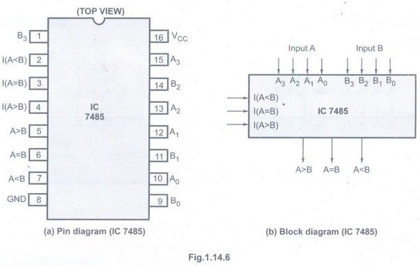
Fig. 1.14.6 shows the logic symbol and
pin diagram of IC 7485. The operation of IC 7485 is described in the function
table, showing all possible logic conditions.
Example 1.14.3
Design an 8-bit comparator using two 7485 ICs. AU: May-07
Solution :Fig.
1.14.7 shows an 8-bit comparator using two 7485 ICs.

Example 1.14.4 Design a 5-bit magnitude comparator using comparator IC 7485. AU May-08, Marks 8
Solution: Truth Table
K-map
Simplification
Implementation
Examples for Practice
Example 1.14.5
Design a 4-bit magnitude comparator to compare two 4-bit numbers. AU May-19,
Marks 7
Example 1.14.6
Explain comparison of n-bit binary numbers.
Review Question
1. Draw the schematic of a magnitude comparator and give its truth table. AU: May-11, Marks 6
Digital Principles and Computer Organization: Unit I: Combinational Logic : Tag: : Combinational Logic - Digital Principles and Computer Organization - Magnitude Comparator
Related Topics
Related Subjects

Digital Principles and Computer Organization
CS3351 3rd Semester CSE Dept | 2021 Regulation | 3rd Semester CSE Dept 2021 Regulation