Basic Electrical and Electronics Engineering: Unit IV: Digital Electronics
Logic Gates
Circuit diagram, Symbol, Truth Table
Logic gates are the basic elements that made up the digital circuits. The logic gates are operate with binary input numbers in order to perform logic functions.
LOGIC GATES
Logic gates are the basic elements that made up the digital circuits. The logic gates are operate with binary input numbers in order to perform logic functions. Gates are digital circuits, the input and output signals have only two states, either low (0) (or) high (1) values. There are three basic logical gates AND, OR and NOT gates.
AND Gate
An AND gate has two (or) more inputs and only one output which is equal to AND product of all inputs figure 4.4 shows the circuit and symbol of a two input AND gate.

The circuit consists of two diode D1 and D2 and a resistance R1 connected as shown in figure 4.4(a). It both inputs A and B are low, then anodes of D1 and D2 are.connected to +5v. As such both diodes D1 and D2 are forward biased and conduct pulling down the output to low value. If one of the input is low, the other being high, the diode with low input conducts and pull down the output to low value the diode with the high input being reversed biased, gets cut-off. If both inputs are high, both diodes being reverse biased get cut-off and supply voltage, high, appears at output. Table 4.2 shows the two input AND gate truth table. It shows both inputs are high the output is high otherwise output is low.
OR Gate
An OR-gate has two (or) more inputs and only one output, which is equal to the OR sum of all inputs. Figure 4.5 shows the circuit of input OR gate and symbol. The circuit consists of two inputs A, B two diodes D1, D2 and resistance R.
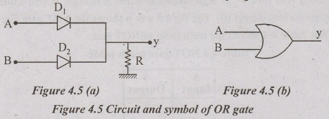
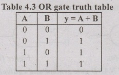
If both the inputs are low (0), then diode D, and D, do not conduct, giving low (0) at y. If any input A (or) B is high, the diode with that high input conducts giving high (1) output. If both the inputs are high, both diodes conduct, giving high (1) output. Table 4.3 shows the truth table of OR gate.
NOT Gate
Not gate has only a single input and always a single output signal. Output logic is the complement of the input logic i.e output is NOT same as input.
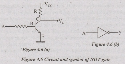
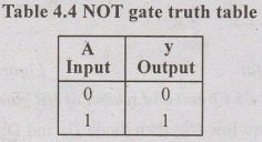
The circuit in figure 4.6(a) shows the CE amplifiers, which act as a switch. Operates in cut off and saturation region. When A is low (0), then transistor gets cut off and is unable to conducts, thus full voltage of Vcc is available at the output terminal. Thus A is low, V0 is high. Whereas when A is high, it will saturate the transistor, give a low output (0). The fig 4.6 a & b shows the NOT gate circuit and symbol. The Table 4.4 shows the truth table of NOT gate.
NAND Gate
NAND gate actually means NOT-AND and implies an AND gate function with a complemented output. A standard logic symbol for a two-input NAND gate and equivalency of NAND gate is shown in fig 4.7(a) & (b).
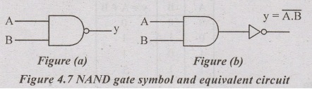
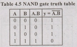
The NAND gate is a universal gate as it can be used to construct an AND gate, an OR gate, and inverter gates. The output of NAND gate is complement of AND gate output. The table 4.5 shows the truth table of NAND gate.
NOR Gate
The term NOR is a constraction of NOT-OR and implies an OR function with complement figure 4.8 (a) & (b) shows the standard symbol and equivalent circuit.
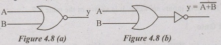
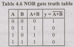
NOR gate also universal gate, i.e NOR gate can be used to construct all basic gates AND, OR and NOT gates. The truth table for a two input NOR gate is shown in Table 4.6.
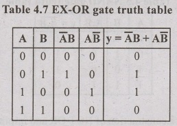
EX-OR Gate
Ex-OR gate is an abbreviation of Exclusion-OR gate. An Ex-OR gate has two (or) more inputs and one output. The standard and symbol and equivalent circuit is show in figure 4.9 (a) & (b).

The output EX-OR gate is logic high when the both inputs are different. When output is low, both inputs are same. It is shown in the table 4.7.
EX-NOR Gate
The term EX-NOR gate is formed by NOT and exclusion OR gate. It is logical equivalent circuit and symbol is shown in figure 4.10 (a) & (b).
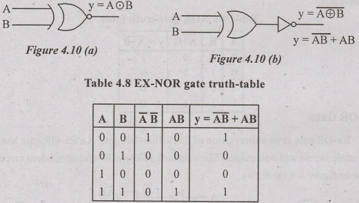
The EX-NOR gate output is high, when the both the inputs are same.Whereas output is low, when inputs are different combination. It is shown in truth table 4.8.
Basic Electrical and Electronics Engineering: Unit IV: Digital Electronics : Tag: : Circuit diagram, Symbol, Truth Table - Logic Gates
Related Topics
Related Subjects

Basic Electrical and Electronics Engineering
BE3251 2nd semester Mechanical Dept | 2021 Regulation | 2nd Semester Mechanical Dept 2021 Regulation

Basic Electrical and Electronics Engineering
BE3251 2nd Semester CSE Dept 2021 | Regulation | 2nd Semester CSE Dept 2021 Regulation