Digital Principles and Computer Organization: Unit II (c): Registers
Johnson or Twisting Ring or Switch Tail Counter
Registers - Digital Principles and Computer Organization
In a Johnson counter, the Q output of each stage of flip-flop is connected to the D input of the next stage.
Johnson or Twisting Ring
or Switch Tail Counter
AU May-07, Dec.-05,06,11,18
• In a Johnson counter, the Q output of each stage of flip-flop is connected to the D input of the next stage.
• The single exception is that the
complement output of the last flip-flop is connected back to the D-input of the
first flip-flop as shown in Fig. 4.7.1.
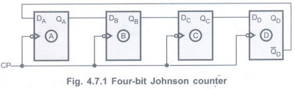
Note Johnson counter
can be implemented with SR or JK flip-flops as well.
• As shown in Fig. 4.7.1 there is a
feedback from the rightmost flip-flop complement output to the leftmost
flip-flop input. This arrangement produces a unique sequence of states.
• Initially, the register (all
flip-flops) is cleared. So all the outputs, QA, QB, QC,
QD
are zero.
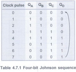
• The output of last stage, QD is
zero. Therefore complement output of last stage, pppppppppp is one. This is
connected back to the D input of first stage. So DA is one.
• The first falling clock edge produces QA=
1 and QB = 0, QC= 0, QD=
0 since
DB, DC, DD are zero.
• The next clock pulse produces QA=
1, QB= 1, QC = 0, QD = 0.
• The sequence of states is summarized
in Table 4.7.1
• After 8 states the same sequence is
repeated.
• In this case, four-bit register is
used. So the four-bit sequence has a total of eight
states.
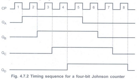
• Fig. 4.7.2 gives the timing sequence
for a four-bit Johnson counter.
• If we design a counter of five-bit
sequence, it has a total of ten states.
• An n-stage Johnson counter will produce
a modulus of 2×n, where n is the number of stages (i.e. flip-flops) in the
counter.
• Johnson counter requires only half the number of flip-flops compared to the standard ring counter. However, it requires more flip-flop than binary counter.
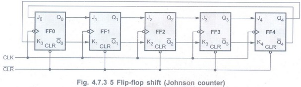
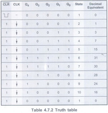
Example 4.7.1 Draw a
5 flip-flop shift (Johnson) counter, its truth table and waveforms. Explain its
operation as a decade counter. AU Dec.-05, Marks 16
Solution:
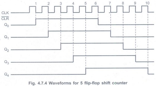
The Fig. 4.7.3 shows the 5-bit shift (Johnson) counter. Since this counter goes
through 10 states, the frequency at the output of last flip-flop is 1/10th of
the clock frequency and hence it is a decade counter.
The Table 4.7.2 shows the truth table
for the 5 flip-flop shift counter and illustrates its operation.
Waveforms:
Review Questions
1. Draw the 4-bit Johnson counter and explain the operation. AU May-07, Dec.-06, Marks 8
2. Design Johnson counter and state its advantages and disadvantages. AU: Dec.-11, Marks 8
3. Explain in detail about 4 bit Johnson counter. AU: Dec.-18, Marks 13
Digital Principles and Computer Organization: Unit II (c): Registers : Tag: : Registers - Digital Principles and Computer Organization - Johnson or Twisting Ring or Switch Tail Counter
Related Topics
Related Subjects

Digital Principles and Computer Organization
CS3351 3rd Semester CSE Dept | 2021 Regulation | 3rd Semester CSE Dept 2021 Regulation