Digital Principles and Computer Organization: Unit III: Computer Fundamentals
Instructions
Computer Fundamentals - Digital Principles and Computer Organization
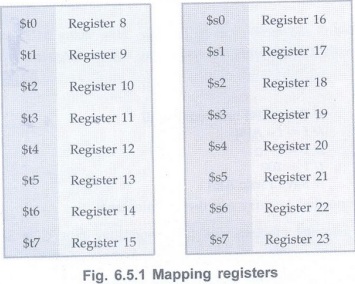
In MIPS assembly language, registers $50 to $s7 map onto registers 16 to 23, and registers $t0 to $t7 map onto registers 8 to 15. The opcode in MIPS instruction set architecture is only 6 bits. This means there are only 64 possible instructions. `
Instructions
AU:
May-18
• In MIPS assembly language, registers
$50 to $s7 map onto registers 16 to 23, and registers $t0 to $t7 map onto
registers 8 to 15 as shown Fig. 6.5.1.
Translating a MIPS Assembly Instruction
into a Machine Instruction
R-Format Instruction
• MIP instruction is divided into
segments called fields. Fig. 6.5.2 shows instruction format for register type
(R- Type) instruction.
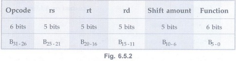
• The opcode in MIPS instruction set
architecture is only 6 bits. This means there are only 64 possible
instructions. `For R-type instructions, an additional 6 bits are used called the
function. Thus, the 6 bits of the opcode and the 6 bits of the function specify
the kind of instruction for R-type instructions.
rd (B25-21): This
is the destination register. The destination register is the register where the
result of the operation is stored.
rs (B20-16) This is
the first source register. The source register is the register that holds one
of the arguments of the operation.
rt (B15-11) :This
is the second source register.
Shift amount
(B10-6): The amount of bits to shift. Used in shift instructions.
Function
(B5-0): An additional 6 bits used to specify the operation, in addition to the
opcode.
Let us translate the instruction add
$to, $s1, $s2 into a machine instruction.
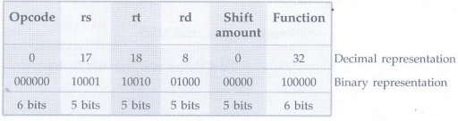
• The first and last fields (containing 0
and 32 in this case) in combination tell the MIPS computer that this
instruction performs addition. The second field gives the number of the
register that is the first source operand of the addition operation (17 = $s1),
and third field gives the other source operand for the addition (18 $s2). The
fourth field contains the number of the register that is to receive the sum (8=
$t0). The fifth field is unused in this instruction, so it is set to 0. Thus,
this instruction adds register $s1 to register $s2 and places the sum in
register $t0.
I-Format Instruction
• A second type of instruction format is
called I-type (for immediate) or I-format and is used by the immediate and data
transfer instructions. The fields of I-format are :
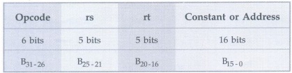
• The 16-bit address means a load word
instruction can load any word within a region of ±215 or 32,768
bytes (± 213 or 8192 words) of the address in the base register rs.
Similarly, add immediate is limited to constants no larger than ±215
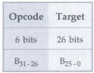
J-Format Instructions
J-type is short for "jump
type". The format of an J-type instruction looks like:
lw $t0,32($s3) # Temporary reg $t0 gets
A[8]
Example:
addi $s1,$s2, 20 // $s1=$s220 Used to add constants
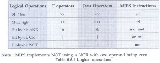
Logical Operations
Table 6.5.1 shows logical operations in
C, Java, and MIPS.
Shift Left and Shift Right Operations
sll $t2,$s0,4// reg $t2 = reg $s0 < 4
bits
if register $s0 contained
0000 0000 0000 0000 0000 0000 0001 10012
= 2510
and the instruction to shift left by 4
was executed, the new value would be:
0000 0000 0000 0000 0000 0001 1001 00002=
40010 This value is stored in $t2. The dual of a shift left is a
shift right.
AND, OR and NOT Operations
AND: A logical
bit-by bit operation with two operands that calculates a 1 only if there is a 1
in both operands.
OR: A logical bit-by
bit operation with two operands that calculates a 1 if there is a 1 in either
operand.
NOT: A logical
bit-by bit operation with one operand that inverts the bits; that is, it
replaces every 1 with a 0, and every 0 with a 1.
NOR: A logical bit-by
bit operation with two operands that calculates the NOT of the OR of the two
operands. That is, it calculates a 1 only if there is a 0 in both operands.
Note that MIPS instruction set includes
NOR (NOT OR) instruction instead of NOT instruction. If one operand is zero,
then it is equivalent to NOT: A NOR 0 = NOT (A OR 0) = NOT (A).
Let us assume the contents of $t1 and
St2 are as follows:
$t1: 0000 0000 0000 0000 0011 1100 0000
00002 and
$t2: 0000 0000 0000 0000 0000 1111 1101
00002 and
$t3: 0000 0000 0000 0000 0000 0000 0000
00002
and $t0,$t1,$t2 $t0: 0000 0000 0000 0000 0000 1100 0000 00002 // $t0 = $t1 & $t2
or $to, $t1, $t2 $t0 : 0000 0000 0000 0000 0011 1111 1101 00002 // $t0 = $t1 | $t2
nor $t0,$t1,$t3$to : 1111 1111 1111 1111 1100 0011 1111 11112 // $t0 = ~($t1 | $t3)
Decision Making AU:
May-18
• MIPS assembly language includes two
decision-making instructions, similar to an if statement with a go to.
• beq register1, register2, L1:
This instruction means go to the statement labeled L1 if the value in register1
equals the value in register2. The mnemonic beq stands for branch if equal.
• bne register1, register2, L1:
It means go to the statement labeled L1 if the value in register1 does not
equal the value in register2. The mnemonic bne stands for branch if not equal.
These two instructions are called conditional branches.
Example 6.5.1
In the following code segment, a, b, c, d and e are variables. If the five variables
f through j correspond to the five registers $50 through $s4, what is the
compiled MIPS code for C code.
If (a==b) c=d+e; else c = d - e;
Solution :
bne $s0, $s1, Else // go to Else if a #b
add $s2,$3,$s4// c=d+e (skipped if a #
b)
j Exit// go to Exit
Else: sub $s2,$s3,$s4// c = de (skipped
if a = b)
Example 6.5.2
Translate the following C code to MIPS assembly code. Use a minimum number of
instructions. Assume that i and k correspond to registers $s3 and $s5 and the
base of the array save is in $s6. What is the MIPS assembly code corresponding
to this C segment?
while (save [i] = = k)
i += 1; AU May-18, Marks 5
Solution :
Loop: sll $t1, $s3, 2// The first step is
to load save[i] into a temporary register
// Temp reg $t1 = i * 4 i.e. multiply
the index i by 4 using
// instruction shift left logical by 2
bits to solve byte
// addressing problem
add $t1, $t1, $s6 // $t1 address of
save[i] - To get the address of save[i],
// we need to add
// $t1 and the base of save in $s6
lw $t0,0($t1)// Temp reg $t0 save[i]
using address load save[i] into a
// temporary register: $t0
bne $t0,$s5, Exit // go to Exit if
save[i]? k
ado $s3,$s3,1// i = i + 1
j Loop // repeat Loop
Exit
Review Questions
1. Explain in brief the issues involved
in the design of an instruction format.
2. Explain the shift instructions
supported by MIP with the help of suitable examples.
3. Explain the logical instructions
supported by MIP with the help of suitable examples.
4. Explain the conditional branch
instructions supported by MIP with the help of suitable examples.
Digital Principles and Computer Organization: Unit III: Computer Fundamentals : Tag: : Computer Fundamentals - Digital Principles and Computer Organization - Instructions
Related Topics
Related Subjects

Digital Principles and Computer Organization
CS3351 3rd Semester CSE Dept | 2021 Regulation | 3rd Semester CSE Dept 2021 Regulation