Digital Principles and Computer Organization: Unit III: Computer Fundamentals
Instruction and Instruction Sequencing
Computer Fundamentals - Digital Principles and Computer Organization
A computer has a set of instructions that allows the user to formulate any data-processing task. To carry out tasks, regardless of whether a computer has 100 instructions or 300 instructions.
Instruction and
Instruction Sequencing
• A computer has a set of instructions
that allows the user to formulate any data-processing task. To carry out tasks,
regardless of whether a computer has 100 instructions or 300 instructions, its
instructions must be capable of performing following basic operations:
• Data transfers between the memory and
the processor registers.
• Arithmetic and logic operations on
data.
• Program sequencing and control.
• I/O control.
Register Transfer Notation
• We have seen that in a computer system
data transfer takes place between processor registers and memory and between
processor registers and I/O system. These data transfers can be represented by
standard notations given below :
• Processor registers are represented by
notations R0, R1, R2,... and so on.
• The addresses of the memory locations
are represented by names such as LOC, PLACE, MEM, etc.
• I/O registers are represented by names such as DATAIN, DATAOUT and so on.
• The contents of register or memory
location are denoted by placing square brackets around the name of the register
or memory location.
• Let us see following examples for clear
understanding.
Example: R2 ← [LOC]
• This expression states that the contents
of memory location LOC are transferred into the processor register R2.
Example: R3 ← [R1] + [R2]
• This expression states that the
contents of processor registers R1and R2 are added and the result is stored
into the processor register R3.
Example: [LOC] ← [R1] - [R2]
• This expression states that the
contents of the processor register R2 is subtracted from processor register
• The notations explained above are commonly known as Register
Transfer Notations (RTN). In these notations, the data represented by the
right-hand side of the expression is transferred to the location specified by
the left hand side of the expression, overwriting the old contents of that
location.
Assembly Language Notations
• Assembly language notations are the
another type of notations used to represent machine instructions and programs.
These notations use assembly language formats. However, register names, names
of memory locations are same as that of register notations.
• Let us see some examples.
Example: MOVE R2, R1
• This expression states that the
contents of processor register R2 are transferred to processor register R1.
Thus the contents register R2 remain unchanged but contents of register R1 are
overwritten.
Example: ADD R1, R2, R3
• This expression states that the
contents of processor registers R1 and R2 are added and the result is stored in
the register R3.
• It is important to note that the above
expressions written in the assembly language notations has three fields:
Operation, source and destination having their positions from left to right.
This order is followed by many computer. But there are many computers in which
the order of source and destination operands is reversed.
Basic Instruction Types
• Each instruction of the CPU contain
specific information fields, which are required to execute it. These
information fields of instructions are called elements of instruction. These
are:
• Operation code : The operation
code field in the instruction specifies the operation to be performed. The
operation is specified by binary code, hence the name operation code or simply
opcode.
• Source / Destination operand:
The source/destination operand field directly specifies the source/destination
operand for the instruction.
• Source operand address: We know
that the operation specified by the instruction may require one or more
operands. The source operand may be in the CPU register or in the memory. Many
times the instruction specifies the address of the source operand so that
operand(s) can be accessed and operated by the CPU according to the
instruction.
• Destination operand address:
The operation executed by the CPU may produce result. Most of the times the
result is stored in one of the operand. Such operand is known as destination
operand. The instruction which produce result specifies the destination operand
address.
• Next instruction address: The
next instruction address tells the CPU from where to fetch the next instruction
after completion of execution of current instruction. For JUMP and BRANCH
instructions the address of the next instruction is specified within the
instruction. However, for other instructions, the next instruction to be
fetched immediately follows the current instruction.
• Computers may have instructions of
several different lengths containing varying number of addresses. According to
address reference there are three address, two address, one address and zero
address reference instructions. Let us see examples of each of them.
Three address instructions :
The three address instruction can be represented symbolically as
ADD A, B, C
where A, B, C are the variables. These
variable names are assigned to distinct locations in the memory. In this
instruction operands A and B are called source operands and operand C is called
destination operand and ADD is the operation to be performed on the operands.
Thus the general instruction format for three address instruction is
Operation Source 1, Source 2,
Destination
The number of bits required to represent
such instruction include:
1. Bits required to specify the three
memory addresses of the three operands. If n-bits are required to specify one
memory address, 3n bits are required to specify three memory addresses.
2.Bits required to specify the
operation.
Two address instructions :
The two address instruction can be symbolically as
ADD A, B
This instruction adds the contents of
variables A and B and stores the sum in variable B destroying its previous
contents. Here, operand A is source operand ; however operand B serves as both
source and destination operand. The general instruction format for two address
instruction is
Operation Source, Destination
To represent this instruction less
number of bits are required as compared to three address instruction. The number
of bits required to represent two address instruction include:
1. Bits required to specify the two
memory addresses of the two operands, i.e. 2n bits.
2. Bits required to specify the
operation.
One address instruction :
The one address instruction can be represented symbolicallyas
ADD B
This instruction adds the contents of
variable A into the processor register called accumulator and stores the sum
back into the accumulator destroying the previous contents of the accumulator.
In this instruction the second operand is assumed implicitly in a unique
location accumulator. The general instruction format for one address
instruction is
Operation Source
Few more examples of one address
instructions are :
LOAD A: This instruction copies the
contents of memory location A into the accumulator.
STORE B: This instruction copies the
contents of accumulator into memory location B.
In one address instruction, it is
important to note that the operand specified in the instruction can be either
source operand or destination operand depending on the instruction. For
example, in LOAD A instruction, the operand specified in the instruction is a
source operand whereas the operand specified in the STORE B instruction is a
destination operand. Similarly, in one address instruction the implied operand
(accumulator) can be either source or destination depending on the instruction.
Zero address instructions:
In these instructions, the locations of all operands are defined implicitly.
Such instructions are found in machines that store operands in a structure
called a pushdown stack.
From above discussion we can easily understand that the instruction with only one address will require less number of bits to represent it, and instruction with three addresses will require more number of bits to represent it. Therefore, to access entire instruction from the memory, the instruction with three addresses requires more memory accesses while instruction with one address requires less memory accesses. The speed of instruction execution is mainly depend on how much memory accesses it requires for the execution. If memory accesses are more, more time is required to execute the instruction. Therefore, the execution time for three address instructions is more than the execution time for one address instructions.
To have a less execution time we have to
use instructions with minimum memory accesses. For this instead of referring
the operands from memory it is advised to refer operands from processor
registers. When machine level language programs are generated by compilers from
high-level languages, the intelligent compilers see that the maximum references
to the operands lie in the processor registers.
Example 6.9.1
Write a program to evaluate the arithmetic statement Y = (A+B) * (C+D) using
three-address, two-address, one-address and zero-address instructions. Solution
:
Using three address instructions
ADD A, B,R1 ;
R1←M[A] + M[B]
ADD C, D,R2 ; R2←M[C] + M[D]
MUL R1, R2,Y ; M[Y]← R1 * R2
Using two address instructions
MOV A, R1 ; R1←M[A]
ADD B, R1 ; R1←R1 + M[B]
MOV C, R2 ; R2←M[C]
ADD D, R2 ; R2←R2+ M[D]
MUL R2, R1 ; R1← R1 R2
MOV R1, Y ; [Y]← R1
Using one address instruction
LOAD
A ; AC←M[A]
ADD
B ; AC←AC+M[B]
STORE
T ; M[T]←AC
LOAD
C ; AC←M[C]
ADD
D ; AC←AC+M[D]
MUL T ; AC←AC*M[T]
STORE Y ; M[Y]←AC
Using zero address instructions
PUSH
A ; TOS←A
PUSH
B ; TOS←B
ADD TOS←(A+B)
PUSH C
; TOS←C
PUSH D
; TOS←D
ADD ; TOS←(C+D)
MUL ; TOS←(C+D)*(A+B)
POP Y ; M[Y]←TOS
Example 6.9.2
Write the program to evaluate the expressionX =A [B+C(D+E)]/ F(G+H)using the
zero address instructions and one address instructions.
Solution :Program using zero address
instructions
PUSH
D ; TOS←D
PUSH
E ; TOS←E
ADD ; TOS←(D+E)
PUSH
C ; TOS←C
MUL ; TOS←C×(D+E)
PUSH
B ; TOS←B
ADD ; TOS←B+C×(D+E)
PUSH A ; TOS←A
MUL ; TOS←A[B+C×(D+E)]
PUSH G ; TOS←G
PUSH H ; TOS←H
ADD ; TOS←G+H
PUSHF ; TOS←F
MUL ; TOS←F× (G + H)
DIV ; TOS A[B+C× (D+ E)]/F× (G + H)
POPX ; M [X] ← TOS
Program using one address instructions
LOAD H ; AC← M[H]
ADD G ; AC←AC + M[G]
MUL F ; AC←AC*M[F]
STORE T ; M[T]←AC
LOAD D ; AC← M[D]
ADD E ; AC←AC + M[E]
ADD B ; AC←AC + M[B]
MUL A ; AC←AC* M[A]
DIV T ; AC←AC/M[T]
STORE Χ ; M[X] ← AC
Example 6.9.3
X = A×B+C×C
Explain how the above expression will be
executed in one address, two address and three address processors in an
accumulator organization.
Solution :
Using one address instruction
LOAD A ; AC← M[A]
MUL B ; AC←AC* M[B]
STORE T ; M[T] ←AC
LOAD C ; AC← M[C]
MUL C ; AC←AC* M[C]
ADD T ; AC←AC + M[T]
STORE X ; M[X] ← AC
Using two address instructions
MOV A, R1 ;
R1←M[A]
MUL B, R1 ;
R1←R1*M[B]
MOV C, R2 ;
R2←M[C]
MUL C, R2 ; R2←R2*M[C]
ADD
R2, R1 ; R1←R1+R2
MOV
R1, X ; M[T]←R1
Using three address instructions
MUL A, B, R1 ;
R1←M[A]*M[B]
MUL C, C, R2 ;
R2←M[C]+M[C]
Add
R1, R1, X ; M[X]←R1*R2
Example 6.9.4
Give reasons to justify using, generally, i) Single address instructions in
8-bit CPU's ii) Double address instruction in 16-bit CPU's iii) Three address
instructions in RISC systems. In each of these systems give assembly language
programs for performing the operation:
data at mem A + data at mem B→ mem C.
Show how the operation C = A + B can be
implemented in a single accumulator computer by i) Three-address instruction
ii) Two-address instruction iii) One-address instruction.
Solution:
The instruction with only single address will require less number of bits to
represent it, and instruction with three address will require more number of
bits to represent it. That is, more address instruction requires more number of
bits to represent it. Generally, CPU should take less number of machine cycles
(preferably only one) to read the instruction. We know that, how many byte/s
CPU can access at a time depends on the data bus width. Therefore, to have less
number of machine cycles to read the instruction we generally use single address
instructions in 8-bit CPUs, double address instructions in 16-bit CPUs. We know
that, RISC systems use long instruction lengths therefore we generally use
three address instructions in RISC systems.
Operation:data
at mem A + data at mem B → mem C
Assembly Language Programs for above
operations are :
Single Address :
LOAD A ; Accumulator←[A]
ADD B ; Accumulator←Accumulator+[B]
STORE C ; C←Accumulator
Double Address :
MOVE B, C ; C←[B]
ADD A, C ; C←[A]+[C]
;
i.e, C←[A]+[B]
Three Address :
ADD A, B, C ; C←[A]+[B]
Example 6.9.5
Write a program which evaluates the expression A×B+C×D in a single accumulator
processor. Assume that processor has load, store, multiply and add instructions
and all the values fit in the accumulator.
Solution :Program for single accumulator
processor :
LOAD A ; AC←M[A]
MUL B ; AC←AC×M[B]
STORE X
; M[X]←AC
LOAD C ; AC←M[C]
MUL D ; AC←AC×M[D]
ADD X ; AC←AC+M[X]
Instruction Execution and Straight Line Sequencing
• We have seen that instruction consists
of opcode or opcode and operand/s or opcode and operand address.
• Every processor has some basic types of
instructions such as data transfer instructions, arithmetic instructions,
logical instructions, branch instructions and so
on.
• To perform a particular task on the
computer, it is programmers job to select and write appropriate instructions
one after the other, i.e. programmer has to write instructions in a proper
sequence. This job of programmer is known as instruction sequencing.
• The instructions written in a proper
sequence to execute a particular task is called program.
• Processor executes a program with the
help of Program Counter (PC). PC holds the address of the instruction to be
executed next.
• To begin execution of a program, the
address of its first instruction is placed into the PC. Then, the processor
control circuits use the information (address ofmemory) in the PC to fetch and
execute instructions, one at a time, in the order of increasing addresses. This
is called straight-line sequencing.
• During the execution of instruction,
the PC is incremented by the length of the current instruction in execution.
For example, if currently executing instruction length is 3 bytes, the PC is
incremented by 3 so that it points to the instruction to be executed next.
Branching
• Every time it is not possible to store
a program in the consecutive memory locations. After execution of decision
making instruction we have to follow one of the two program sequences.
• In such cases we can not use
straight-line sequencing. Here, we have to use branch instructions to transfer
the program control from one straight-line sequence to another straight-line
sequence of instruction, as shown in following program.
• For example, see the program given for
operation |A – B|. In this program, we have to check whether A > B or B >
A and accordingly we have to perform operation
A- B or B - A.
MOV NUM1, R0 ; Get the number 1 into R0
MOV NUM2, R1 ; Get the number 2 into R1
CMP R0, R1 ; NUM1-NUM2
JB NEXT ; If NUM1 < Num2
; Jump
to another program sequence
SUB R0, R1 ; NUM2← NUM2- NUM1
MOV R2, R1 ; Store the result in R2
:
:
SUB R1, R0 ; NUM2← NUM2- NUM1
MOV R2, R0 ; Store the result in R2
• In the above program we have used JB
NEXT instruction to transfer the program control to the instruction SUB R1, RO
if NUM1 is less than NUM2. Thus we have decided to branch the program control
after checking the condition. Such branch instructions are called conditional
branch instructions.
• In branch instructions the new address
called target address or branch target is loaded into PC and instruction is
fetched from the new address, instead of the instruction at the location that
follows the branch instruction in sequential address order.
• The conditional branch instructions are
used for program looping. In looping, the program is instructed to execute
certain set of instructions repeatedly to execute a particular task number of
times. For example, to add ten numbers stored in the consecutive memory
locations we have to perform addition ten times.
• The program loop is the basic structure
which forces the processor to repeat a sequence of instructions. Loops have four
sections.
1. Initialization section.
2. Processing section.
3. Loop control section.
4. Result section.
1. The initialization section
establishes the starting values of
• loop counters for counting how many
times loop is executed,
• address registers for indexing which
give pointers to memory locations and
• other variables.
2. The actual data manipulation occurs
in the processing section. This is the section which does the work.
3. The loop control section updates
counters, indices (pointers) for the next iteration.
4. The result section analyzes and
stores the results.

Note: The processor
executes initialization section and result section only once, while it may
execute processing section and loop control section many times. Thus, the
execution time of the loop will be mainly dependent on the execution time of
the processing section and loop control section. The flowchart 1 shows typical
program loop. The processing section in this flowchart is always executed at least
once. If you interchange the position of the processing and loop control
section then it is possible that the processing section may not be executed at
all, if necessary. Refer flowchart 2.
Conditional Codes
• The condition code flags are used to store
the results of certain condition when certain operations are performed during
execution of the program. The condition code flags are stored in the status
registers. The status register is also referred to as flag register.
• ALU operations and certain register
operations may set or reset one or more bits in the status register.
• Status bits lead to a new set of
microprocessor instructions. These instructions permit the execution of a
program to change flow on the basis of the condition of bits in the status
register. So the condition bits in the status register can be used to take
logical decisions within the program. Some of the common condition code flags
are :
1. Carry/Borrow:
The carry bit is set when the summation of two 8-bit numbers is greater than
1111 1111 (FFH). A borrow is generated when a large number is subtracted from a
smaller number.
2. Zero:
The zero bit is set when the contents of register are zero after any operation.
This happens not only when you decrement the register, but also when any
arithmetic or logical operation causes the contents of register to be zero.
3. Negative or sign:
In 2's complement arithmetic, the most significant bit is a sign bit. If this
bit is logic 1, the number is negative number, otherwise a positive number. The
negative bit or sign bit is set when any arithmetic or logical operation gives
a negative result.
4. Auxiliary carry:
The auxiliary carry bit of status register is set when an addition in the first
4-bits causes a carry into the fifth bit. This is often referred as half carry
or intermediate carry. This is used in the BCD arithmetic.
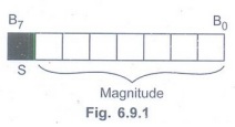
5. Overflow Flag:
In 2's complement arithmetic, most significant bit is used to represent sign
and remaining bits are used to represent magnitude of a number (see Fig. 6.9.1).
This flag is set if the result of a signed operation is too large to fit in the
number of bits available (7-bits for 8-bit number) to represent it.
For example, if you add the 8-bit signed
number 01110110 (+118 decimal) and the 8-bit signed number 00110110 (+ 54
decimal). The result will be 10101100 (+ 172 decimal), which is the correct
binary result, but in this case it is too large to fit in the 7-bits allowed
for the magnitude in an 8-bit signed number. The overflow flag will be set
after this operation to indicate that the result of the addition has overflowed
into the sign bit.
6. Parity:When
the result of an operation leave the indicated register with an even number of
1's, parity bit is set.
Generating Memory Addresses
• The address of the memory can be
specified directly within the instruction. For example, MOV [2000H], R1. In
this instruction the memory address is fix; it can not be dynamically changed
in the program itself. There are some situations where we need to change the
memory address dynamically.
• Let us see the example program. In this
program the contents from the array of data are added to get the total sum of
all array elements.
• We know for this we have repeat the add
instruction number of times equal to the. array elements and each time we have
to add a number from a new successive memory location.
• Every time the address of memory is
different. So to change the address of memory each time when we enter the loop
address variable is used. Such addressing is called indirect addressing. For
example, ADD R1, [R2].
• Here, the contents of R2 register are
used as an address of memory location. By incrementing the contents of register
R2 it is possible to change the memory address each time we enter the loop.
• Note:
The instruction used in the program given below specifies first destination
operand and then the source operand.
MOV R2, Array_start ; Load the starting
address of the array
MOV R0, Count ; Initialize the counter
MOV R1, 0 ; Result = 0
ADD R1, [R2] ; Result ← Result + array
element
INC R2 ; increment memory pointer
DEC R0 ; Decrement count
JNZ BACK ; if count 0, repeat
Review Questions
1. What is register transfer notations?
Give examples.
2. Explain basic instruction types with
the help of examples.
3. What are condition code flags?
Explain the use of them.
4. Mention four types of operations
required to be performed by instruction in a computer. What are the basic types
of instruction formats? Give an example for each.
5. What is straight line sequencing?
Explain with an example.
6. What are condition code flags?
Explain the four commonly used flags.
7. What do you mean by branching?
Digital Principles and Computer Organization: Unit III: Computer Fundamentals : Tag: : Computer Fundamentals - Digital Principles and Computer Organization - Instruction and Instruction Sequencing
Related Topics
Related Subjects

Digital Principles and Computer Organization
CS3351 3rd Semester CSE Dept | 2021 Regulation | 3rd Semester CSE Dept 2021 Regulation