Introduction to Operating Systems: Unit IV(a): Storage Management
I/O Hardware
Storage Management - Introduction to Operating Systems
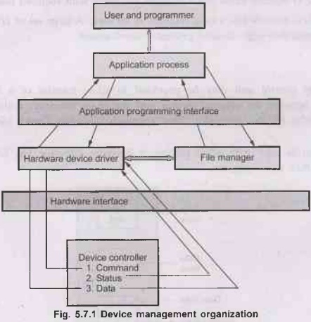
Device management is the part of the operating system responsible for directly manipulating the hardware devices. Device management is implemented through stab the interaction of a device driver and interrupt routine.
I/O Hardware
• Device management is the part of the
operating system responsible for directly manipulating the hardware devices.
Device management is implemented through stab the interaction of a device
driver and interrupt routine.
• Fig. 5.7.1 shows the device management
organization.
•
To start I/O operation, the CPU loads appropriate instructions and values into
the registers of the device controller via the device driver. The device
controller examines the registers :
1. The request may be a read or write
instruction.
2. The controller performs the
appropriate actions.
Once
finished, the controller triggers, an interrupt. The interrupt handler services
the interrupt once it occurs.
1. Programmed I/O 2. Interrupt driven
I/O 3. Direct Memory Access (DMA).
Evolution
of I/O Function
1.
Peripheral devices are directly controlled by CPU.
2. Input-output module or controller
module is added. Processor uses programmed I/O with interrupts.
3. Same as step 2 but only interrupt are
used.
4. The I/O takes direct control of
memory by using DMA. It will transfer data by using DMA.
5.
The
I/O module looks like a separate processor with required instruction.
6.
The I/O module has a local memory of its own. A large set of I/O devices can be
controlled with minimal processor involvement.
DMA
•
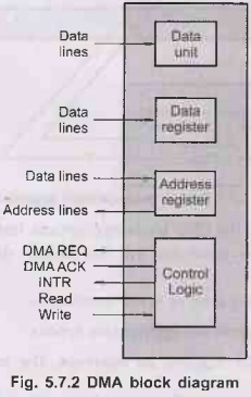
A special control unit may be provided to allow transfer of a block of data
directly between an external device and the main memory, without continous
intervention by the processor. This approach is called Direct Memory Access
(DMA).
• DMA can be used with either polling or
interrupt software. Fig. 5.7.2 shows the typical DMA block diagram.
• DMA is particularly useful on devices
like disks, where many bytes of information can be transferred in single I/O
operations.
• When used in conjuction with an
interrupt, the CPU is notified only after the mote entire block of data has
been transferred.
• For each byte or word transferred,
it must provide the memory address and all the bus signals that control the
data transfer.
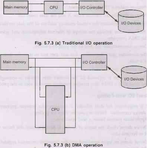
•
Following Fig. 5.7.3 shows the difference between traditional I/O and DMA.
•
DMA mechanism can be configured in a variety of ways.
1.
Single bus, detached DMA
• All the modules use same system bus.
• This configuration is inefficient but
inexpensive.
• It uses programmed I/O to exchange
data between memory and an I/O module through the DMA module.
2.
I/O bus
• I/O bus provide easily expandable
configuration.
• It reduces number of I/O interfaces in the DMA module.
•
Exchange of data between the DMA and I/O module takes place off the system
DMA
data transfer operation
Program →
P
Device → D
1. Program makes a DMA setup request.
2.
Program deposits the address value A and the data count (d).
3. Program also indicates the virtual
memory address of the data on disk.
4.
DMA controller records the receipt of relevant information and acknowledges the
DMA complete.
5.
Device communicates the data to the controller buffer.
6.
The controller grabs the address bus and data bus to store the data, one word
at a time.
7.
Data count is decremented.
8. The above cycle is repeated till the
desired data transfer is accomplished. At the same time a DMA data transfer
complete signal is sent to the process.
Direct I/O with Polling
• CPU is responsible for data
transfer. It transfers data between primary memory and device controller. Following
are the steps for polling :
1. Application process issues a read
operation.
2. Device driver check the status of
device. If device is busy, the driver waits for it to become idle.
3. Driver stores an input command into
the controller command register. It starts the device.
4.
Driver continuously read the status register while waiting for the device to
complete its operations.
5.
Driver copies the content of the controller data register into the user process
space.
Interrupt Driven I/O
• When interrupt I/O is used, the CPU
is free to ignore the I/O module until the interrupt signal a received.
The only added overhead is processing a single interrupt when the I/O
operation completes.
•
In this method the program issues an I/O command and than continues to execute
until it is interrupted by the I/O hardware to signal the end of I/O operation.
Here the program enters a wait loop in which it repeatedly checks the device
status. During this process the processor is not performing any useful
computation.
•
There
are many situations where tasks can be performed while waiting for an I/O
device to be ready, to allow this the I/O device should alert the processor
when it becomes ready. It can be done by sending a hardware signal
called an interrupt.
• The routine executed in response to an
interrupt request is called Interrupt Service Routine (ISR). The processor
first completes execution of instruction then it loads the program counter with
the address of 1st instruction of ISR.
•
In a multiprogramming system the wasted CPU time could be used by another process;
because the CPU is used by other processes in addition to the one waiting ass
for the I/O operation completion, in multiprogramming system may result a bris
sporadic detection of I/O completion; this may be remedied by use of
interrupts.
• The reason for incorporating the
interrupts into computer hardware is to eliminate the need for a device driver
to constantly poll the CSR.
Steps
for performing an input operation
• The
application process requests a read operation.
• The device driver queries the CSR to
find out if the device is idle; if busy, then it waits until the device becomes
idle.
•
The driver stores an input command into the controller's command register, thus
starting the device.
• When this part of the device driver
completes its work, it saves information regarding the operation it began in
the device status table; this table contains an entry for each device in
system; the information written into this table contains the return address of
the original call and any special parameters for the I/O operation; the CPU,
after is doing this, can be used by other program, so the device manager
invokes the scheduler part of the process manager. It then terminates.
• The device completes the operation and
interrupts the CPU, therefore causing an interrupt handler to run.
•
The interrupt handler determines which device caused the interrupt; it then
branches to the device handler for that device.
•
Device driver retrieves the pending I/O status information from the device
status table. The device driver copies the content of the controller's data
register(s) into the user process's space.
• The device handler returns the control to the application process.
Introduction to Operating Systems: Unit IV(a): Storage Management : Tag: : Storage Management - Introduction to Operating Systems - I/O Hardware
Related Topics
Related Subjects
Introduction to Operating Systems
CS3451 4th Semester CSE Dept | 2021 Regulation | 4th Semester CSE Dept 2021 Regulation