Theory of Computation: Unit I: Automata and Regular Expressions
Finite Automata (FA)
Automata and Regular Expressions - Theory of Computation
A finite automata is a collection of 5-tuple (Q, Σ, δ, q0, F)
Finite Automata (FA)
Definition
A
finite automata is a collection of 5-tuple (Q, Σ, δ, q0, F) where,
Q
is a finite set of states, which is non empty.
Σ
is input alphabet, indicates input set.
Q0
is an initial state and q0 is in Q i.e. q0 ϵ Q.
F
is a set of final states.
δ
is a transition function or a mapping function. Using this function the next
state can be determined.
Finite Automata Model
•
The finite automata can be represented using
i) Input tape -
It is a linear tape having some number of cells. Each input symbol is placed in
each cell.
ii) Finite control -
The finite control decides the next state on receiving particular input from
input tape. The tape reader reads the cells one by one from left to right and
at a time only one input symbol is read. (Refer Fig. 1.5.1)

•
For example: suppose current state
is q, and suppose reader is reading the symbol 'a' then it is finite control
which decides what will be the next state at input 'a'. The transition from
current state q with input w to next state q' producing w' will be represented
as,
(q,
w) Ⱶ (q', w')
If
w is a string and M is a finite automata, then w is accepted by the FA
iff (w, s) Ⱶ (q, ε)
with
q as final state.
•
The set of strings accepted by a FA given by M then M is accepted by language
L. The acceptance of M by some language L is denoted by L (M).
•
A machine M accepts a language L iff,
L
= L (M).
Representation of Finite Automata
The
strings and languages can be accepted by a finite automata, when it reaches to
a final state. There are two preferred notations for describing automata :
1. Transition diagram
A
transition diagram or transition graph can be defined as collection of –
1)
Finite set of states K.
2)
Finite set of symbols Σ.
3)
A non empty set S of K. It is called start state.
4)
A set F ![]() K of final states.
K of final states.
5) A transition function K×A →K with K as state and A as input from Σ*

The
notations used in transition diagram are -
For example:
The
FA can be represented using transition graph. The machine initially is in start
state S0 then on receiving input 0 it changes to state S1.
From S0 receiving input 1 the machine changes its state to S4.
The state S2 is a final state or accept state. When we trace the
input for transition diagram and reach to a final state at end of input string
then it is said that the given input is accepted by transition diagram.

Another example:

We
have drawn a transition diagram for the input aabb.
Note
that the start state is S0 and final state is S4. The
input set is Σ = {a,b}. The states S1, S2, S3
are all intermediate states.
2. Transition table
This
is a tabular representation of finite automata. For transition table the transition
function is used.
For example:
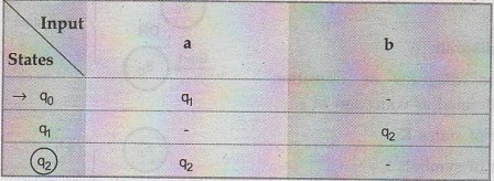
The
rows of the table corresponds to states and columns of the table correspond to
inputs. Here q0 is start state, q2 is final state.
Types of Automata

There
are two types of finite automata -
i)
Deterministic Finite Automata.
Theory of Computation: Unit I: Automata and Regular Expressions : Tag: : Automata and Regular Expressions - Theory of Computation - Finite Automata (FA)
Related Topics
Related Subjects
Theory of Computation
CS3452 4th Semester CSE Dept | 2021 Regulation | 4th Semester CSE Dept 2021 Regulation