Digital Principles and Computer Organization: Unit III: Computer Fundamentals
Encoding of Machine Instructions
Computer Fundamentals - Digital Principles and Computer Organization
In previous sections we have seen various instructions supported by processor. These instructions are written in assembly language format.
Encoding of Machine Instructions
AU: July-18
• In previous sections we have seen
various instructions supported by processor. These instructions are written in
assembly language format. Before execution of these instruction we have to
convert assembly language instruction into its machine language form because
processor only understands machine language.
• We have also seen that instruction
constitutes operation code (opcode) and one or more operands. The operand may
be immediate number, address, processor register or processor register used to
point the memory address.
• To represent each instruction with all
it details, each instruction has an unique machine code. The machine code has
details of the operation to be performed and operand's or address of the
operands. These fields in the machine code are represented by compact bit
pattern by forming an encoded code for each field. Machine code also contains
the information about the addressing mode used in the instruction.
Encoding Instructions into 32-bit words
• We have seen instructions that perform
operations such as add, subtract, move, shift, rotate, and branch. These
instructions may use operands of different sizes, such as 32-bit and 8-bit
numbers or 8-bit ASCII-encoded characters.
• The type of operation that is to be
performed and the type of operands used may be specified using an encoded
binary pattern referred to as the OP code for the given instruction. Suppose
that 8 bits are allocated for this purpose, giving 256 possibilities for
specifying different instructions. This leaves 24 bits to specify the rest of
the required information.
• Let us examine some typical cases. The
instruction ADD R1, R2 has to specify the registers R1 and R2, in addition to
the OP code. If the processor has 16 registers, then four bits are needed to
identify each register.
• Additional bits are needed to indicate
that the Register addressing mode is used for each operand. The instruction
Move 24(R0), R5 requires 16 bits to denote the OP code and the two registers,
and some bits to express that the source operand uses the Index addressing mode
and that the index value is 24.
• The shift instruction LShiftR #2, R0
and the move instruction Move #$3A, R1 have to indicate the immediate values 2
and #$3A, respectively, in addition to the 18 bits used to specify the OP code,
the addressing modes, and the register. This limits the size of the immediate
operand to what is expressible in 14 bits.
• Consider next the branch instruction
Branch >0 LOOP. Again, 8 bits are used for the OP code, leaving 24 bits to
specify the branch offset.
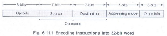
In all these examples, the instructions
can be encoded in a 32-bit word. There is an 8-bit Op-code field and two 7-bit
fields for specifying the source and destination operands. The 7-bit field
identifies the addressing mode and the register involved (if any). The
"Other info" field allows us to specify the additional information
that may be needed, such as an index value or an immediate operand.
Various Instruction Formats
Fig. 6.11.2 shows various instructions
formats: One word instruction, two word instruction and three operand
instruction.

Review Question
Digital Principles and Computer Organization: Unit III: Computer Fundamentals : Tag: : Computer Fundamentals - Digital Principles and Computer Organization - Encoding of Machine Instructions
Related Topics
Related Subjects

Digital Principles and Computer Organization
CS3351 3rd Semester CSE Dept | 2021 Regulation | 3rd Semester CSE Dept 2021 Regulation