Digital Principles and Computer Organization: Unit I: Combinational Logic
Encoders
Combinational Logic - Digital Principles and Computer Organization
An encounter is a digital circuit that performs the inverse operation of a decoder. An encoder has (or fewer) input lines and n output lines.
Encoders
AU: Dec-06,10,12,14,18, May-07,08,10,19
• An encounter is a digital circuit that
performs the inverse operation of a decoder.
•An encoder has
•In encoder the output lines generate
the binary code corresponding to the input value.
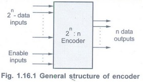
•The Fig. 1.16.1 shows the general
structure of the encoder circuit. As shown in the Fig. 1.16.1 the decoded
information is presented as
Decimal to BCD Encoder
• The decimal to BCD encoder,usually has
ten input lines andfour output lines.
• The decoded decimal data acts as an
input for encoder and encoded BCD output is available on the four output lines.
• The Fig. 1.16.2 shows the logic symbol
for decimal to BCD encoder IC, IC 74XX147.
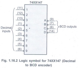
• It has nine input lines and four output
lines.
• Both input and output lines are
asserted active low.
• It is important to note that there is
no input line for decimal zero. When this condition occurs, all output lines
are 1.
• The function table for the 74XX147 is
shown in Table 1.16.1.

x indicates don't care condition
Priority Encoder
• A priority encoder is an encoder circuit
that includes the priority function. In priority encoder, if two or more inputs
are equal to 1 at the same time, the input having the highest priority will
take precedence.
• Table 1.16.2 shows truth table of 4-bit
priority encoder.

•Table 1.16.2 shows
•The
•The output for
•The output V (a valid output indicator)
indicates, one or more of the inputs are equal to 1. If all inputs are 0, V is
equal to 0, and the other two outputs
(
K-map simplification

Octal to Binary Encoder
• Fig. 1.16.5 shows octal to binary
encoder. It has eight inputs, one for each octal digit, and three outputs that
generate the corresponding binary code.
•In encoders it is assumed that only one
input has a value of 1 at any given time; otherwise the circuit is meaningless.
•Table 1.16.3 shows the truth table of
octal to binary converter.

• The circuit has one more ambiguity that
when all inputs are 0s the outputs are 0s. The zero output can also be
generated when
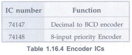
Encoder ICs
Review Questions
1. Define encoder. AU: Dec.-06,
May-10, Marks 2
2. Write a note on encoders.
3. Explain decimal to BCD encoder with
logic symbol and truth table.
4. What is priority encoder? AU:
May-07, 08, Dec.-10,14, Marks 2
5. Explain the octal to binary encoder.
6. Design a 4-input priority encoder. AU
Dec.-12, May-19, Marks 6
7. Explain in detail about encoders. AU:
Dec.-18, Marks 7
Digital Principles and Computer Organization: Unit I: Combinational Logic : Tag: : Combinational Logic - Digital Principles and Computer Organization - Encoders
Related Topics
Related Subjects

Digital Principles and Computer Organization
CS3351 3rd Semester CSE Dept | 2021 Regulation | 3rd Semester CSE Dept 2021 Regulation