Basic Electrical and Electronics Engineering: Unit IV: Digital Electronics
Encoder
Operation, Block diagram, Logic Circuit, Example, Truth Table | Digital Electronics
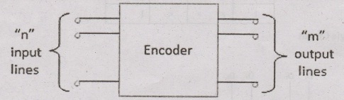
Encoder is a combinational circuit which is designed to perform the inverse operation of the decoder. An encoder has n number of input lines and m number of output lines.
ENCODER
Encoder
is a combinational circuit which is designed to perform the inverse operation
of the decoder. An encoder has n number of input lines and m number of output
lines. An encoder produces an m bit binary code corresponding to the digital
input number. The encoder accepts an n input digital word and converts it into
an m bit another digital word.
Block diagram
Examples
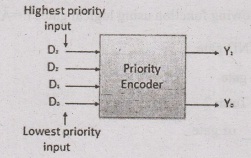
Priority Encoder
This
is a special type of encoder. Priority is given to the input lines. If two or
more input line are 1 at the same time, then the input line with highest
priority will be considered. There are four input D0, D1,
D2, D4 and two output Y0, Y1. Out
of the four input D3 has the highest priority and D0 has
the lowest priority. That means if D3 = 1 Y, = 1 then Y1
Y1 = 11 irrespective of the other inputs. Similarly if D3
= 0 and D2 = 1 then Y0 Y1 = 10 irrespective of
the other inputs.
Block diagram
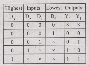
Truth Table
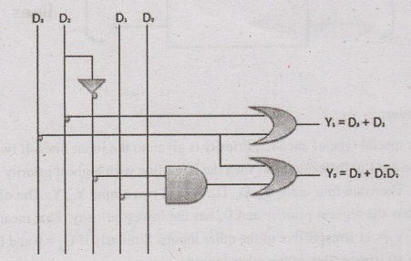
Logic Circuit
Representation of logical function
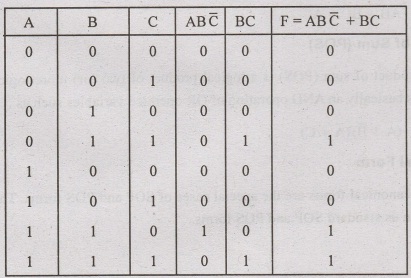
Implement
two following function using logical gates F = Ā B+ AB
Term
1 = Ā B → AND gate
Term
2 = AB AND gate
F
= Term 1 + Term 2
Logical diagram
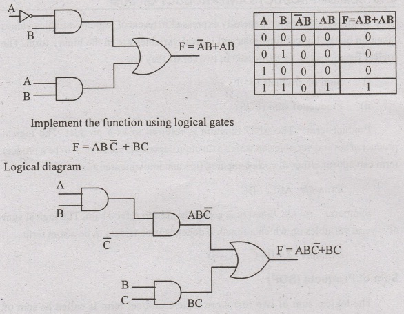
Truth Table
Basic Electrical and Electronics Engineering: Unit IV: Digital Electronics : Tag: : Operation, Block diagram, Logic Circuit, Example, Truth Table | Digital Electronics - Encoder
Related Topics
Related Subjects

Basic Electrical and Electronics Engineering
BE3251 2nd semester Mechanical Dept | 2021 Regulation | 2nd Semester Mechanical Dept 2021 Regulation

Basic Electrical and Electronics Engineering
BE3251 2nd Semester CSE Dept 2021 | Regulation | 2nd Semester CSE Dept 2021 Regulation