Digital Principles and Computer Organization: Unit II (d): Counters
Design of Synchronous Counters
Counters - Digital Principles and Computer Organization
Determine the number of flip-flops needed. If n represents number of flip-flops 2n≥ number of states in the counter. Choose the type of flip-flops to be used.
Design of Synchronous
Counters
AU: Dec.-03, 07, 09, 11, 12, 14, 15,
16,19, May-03, 04, 05, 10, 11, 14, 15, 16, 17
1. Determine the number of flip-flops
needed. If n represents number of flip-flops 2n≥ number of states in
the counter.
2. Choose the type of flip-flops to be
used.
3. Using excitation table for selected
flip-flop determine the excitation table for the
counter.
4. Use K-map or any other simplification
method to derive the flip-flop input functions.
5. Draw the logic diagram.
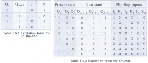
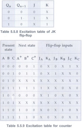
Example 5.5.1
Design a MOD-5 synchronous counter using JK flip-flops and implement it.Also
draw the timing diagram. AU May-16, 17, Marks 16
Solution:
Step 1:
Determine the number of flip-flop needed
Flip-flops required are
2n≥ N
Here N = 5 n = 3 i.e. three flip-flops are required.
Step 2:
Type of flip-flop to be used: JK
Step 3:Determine
the excitation table for the counter.
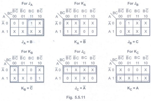
Step 4:K-Map
simplification

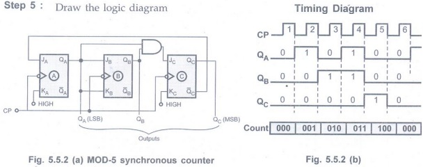
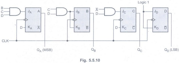
Step 5:Draw
the logic diagram
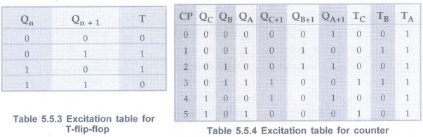
Example 5.5.2
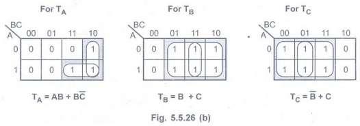
Design divide by 6 counter using T-flip-flops. Write state table and reduce
the expression using K-map.
Solution :
Step 1:
Determine the number of flip-flops needed.
For designing mod 6 counter using the
formula
2n≥ N
Here N = 6 n = 3 i.e. 3 flip-flops are required.
Step 2:Type
of flip-flops to be used: T
Step 3:Determine
the excitation table for counter.
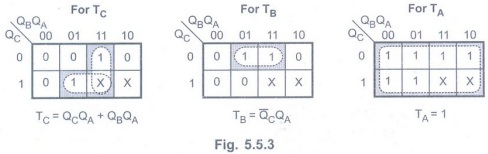
Step 4:
K-map simplification.
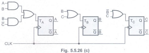
Step 5:
Draw the logic diagram.
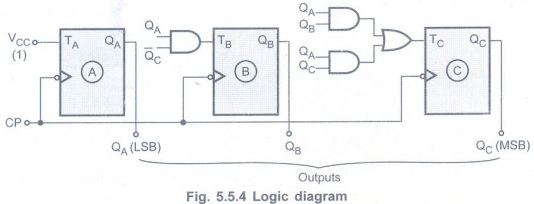
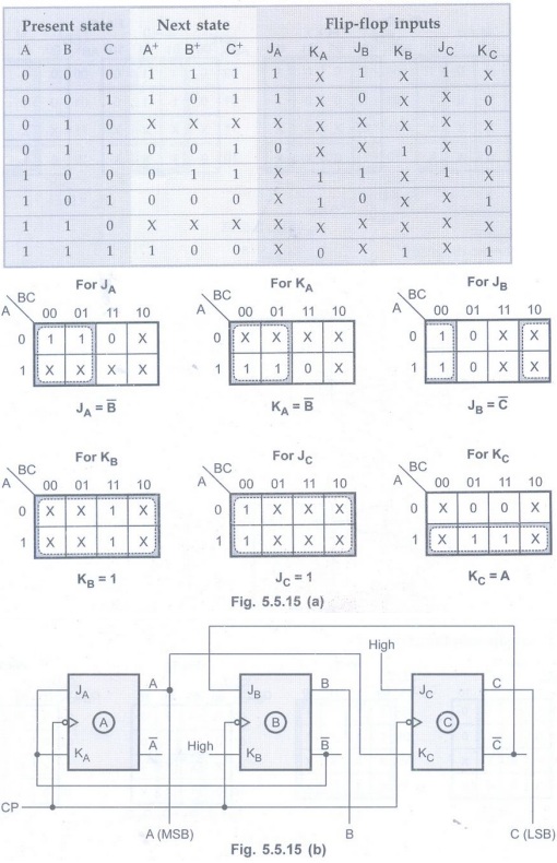
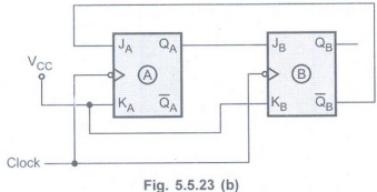
Example 5.5.3
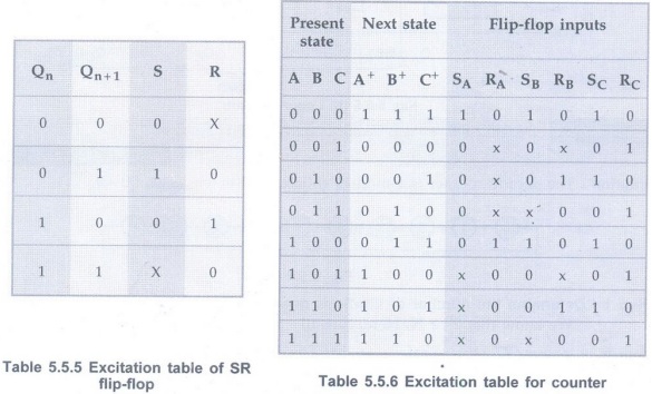
Using positive edge triggering SR flip-flops design a counter which counts
in the following sequence:
000, 111, 110, 101, 100, 011, 010, 001,
000,…..
Solution :
Step 1:Determine
the number of flip-flops needed
We know that2n≥ N. Here, N =
8 therefore n = 3
Step 2:
Type of flip-flop to be used: SR
Step 3: Determine
the excitation table for counter.
Here, the next state for each present
state is written according to given sequence. For example, the next state for
the present state 000 is 111.
Step 4:
K-map simplification.
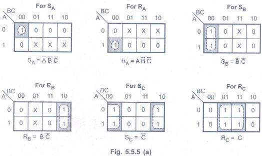
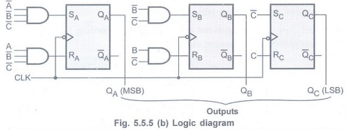
Step 5: Draw
logic diagram
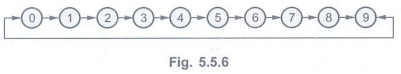
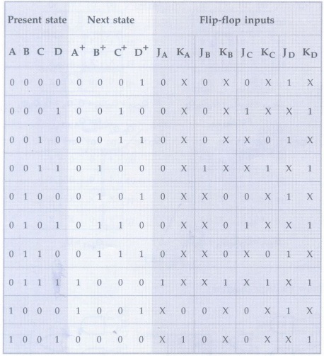
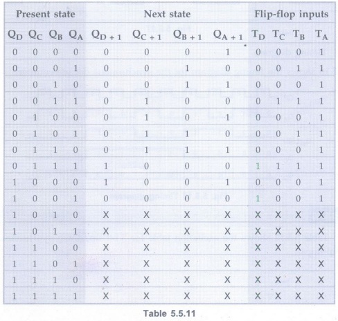
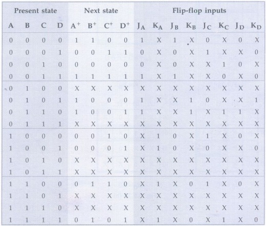
Example 5.5.4 Design a synchronous decade counter using D flip-flop. AU May-15, Marks 16
Solution:
The decade counter is a mod-10 counter. It has ten states: 0 - 9.
Step 1:
Determine the number of flip-flops needed.
We know that 2n ≥ N. Here, N =
10 therefore n = 4 i.e. 4 flip-flops needed.
Step 2:
Type of flip-flops to be used: D
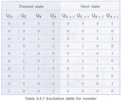
Step 3:Determine
the excitation table for counter.
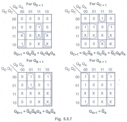
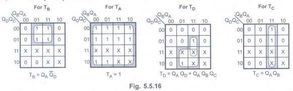
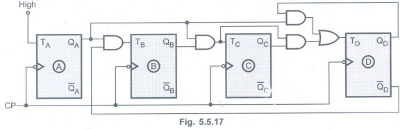
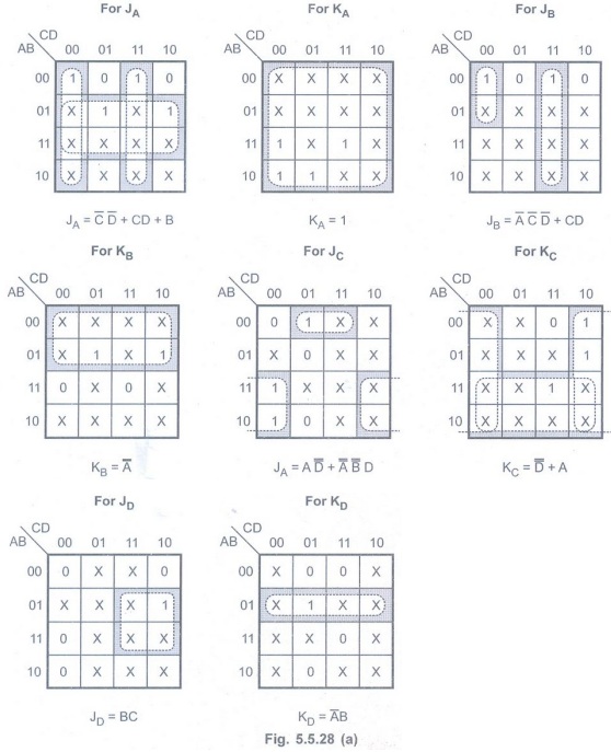
Step 4:
K-map simplification
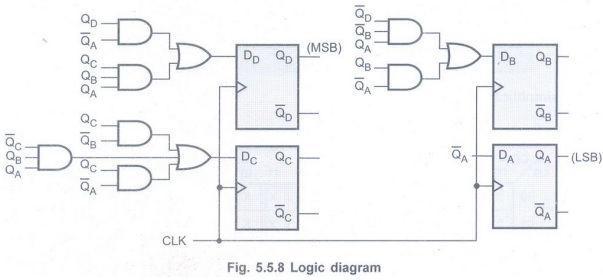
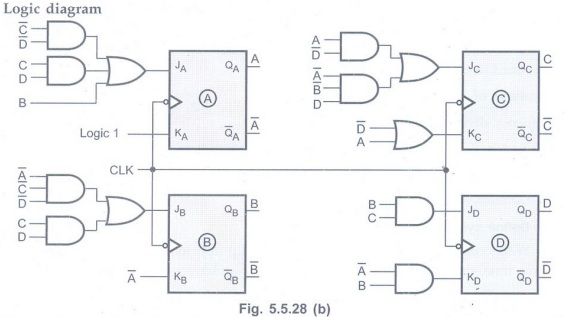
Step 5: Draw
the logic diagram.
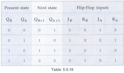
Example 5.5.5
Design a MOD-10 synchrnous counter using JK flip-flops. Write execution table
and state table. AU: Dec.-14, 16, Marks 10
Solution :
Flip-Flops required = 4
Execution Table
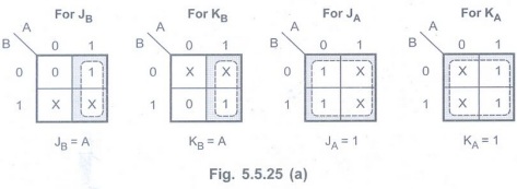
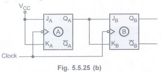
K-map simplification

Implementation
Example 5.5.6
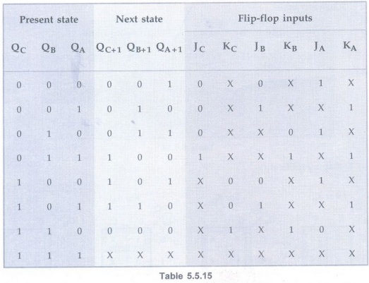
Design a counter with the sequence 0, 1, 3, 7, 6, 4, 0.
Solution :
Step 1:Determine
the number of flip-flops needed. Here, counter should count maximum count = 7 =
(111)2, which is 3-bit. Thus, we need 3-flip-flops.
Step 2:
Flip-flops to be used: JK.
Step 3:Determine
the excitation table for counter. Here, the next state for each present state
is written according to given sequence. For example, the next state for the
present state 3 (011) is 7 (111). The counts which are not in sequence are
treated as don't cares.
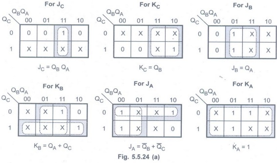
Step 4:
K-map simplification
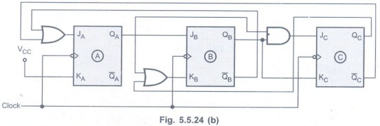
Step 5:
Draw logic diagram.
Example 5.5.7
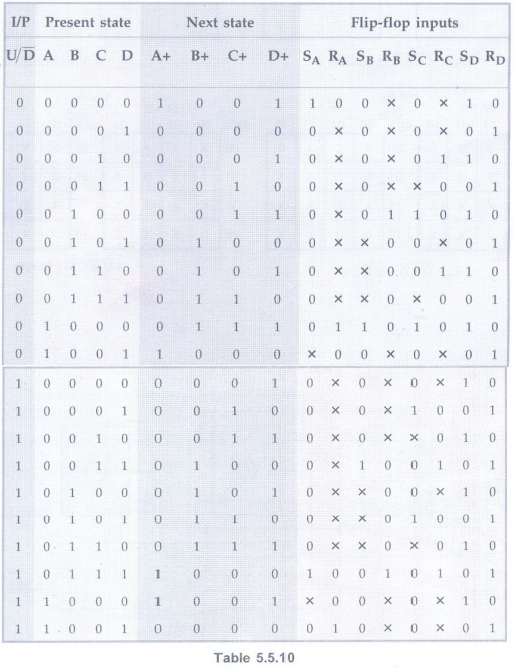
Design a BCD up/down counter using SR flip-flops.
Solution :
Step 1:
Number of flip-flops needed = 4
Step 2: Flip-flops to be used = SR
Step 3: Excitation table for counter
Step 4:
K-map simplification
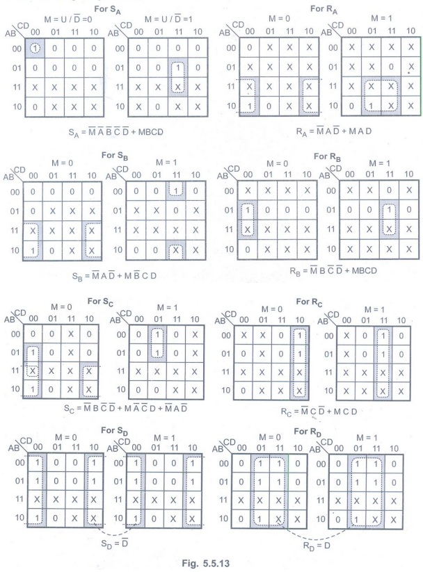
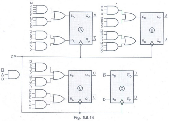
Step 5:Logic
diagram
Example 5.5.8
Design a synchronous counter using JK flip-flop to count the following sequence
7, 4, 3, 1, 5, 0, 7 .... AU: Dec.-14, Marks 16
Solution :
Step 1:
Since 23 > 7, three flip-flops are required
Step 2:
Flip-flops to be used: JK
Step 3:
Excitation table for counter
Example 5.5.9
Design and implement a synchronous decade counter using T flip-flop. Draw the
timing diagram.
Solution :
Step 1:
Since N = 10, n = 4 i.e. flip-flops needed
Step 2:
Flip-flops to be used: T
Step 3:
Determine excitation table for counter
Step 4:
K-map simplification
Step 5:
Logic diagram
Step 6:
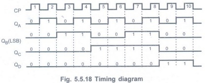
Timing diagram
Fig. 5.5.18 shows the timing diagram for
the synchronous decade counter.
Example 5.5.10
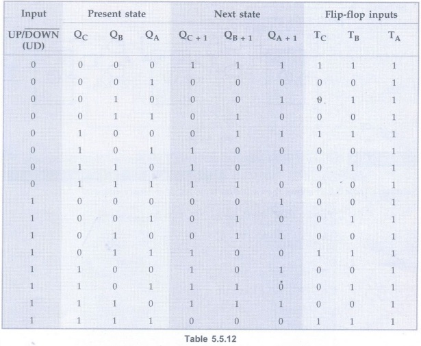
Design a 3-bit synchronous updown counter using T flip-flops.
Solution :Table
5.5.12 shows the excitation table for 3-bit up/down synchronous counter using T
flip-flops.
Excitation table
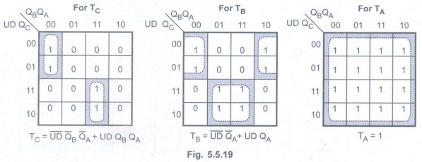
K-map simplification
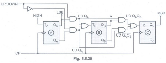
Logic diagram
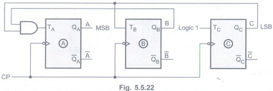
Example 5.5.11
Design a three bit binary counter using T flip-flops and draw the diagram. AU:
Dec.-09, 11, 12, 15, 19, May-16, Marks 16
Solution :
Table 5.5.13 shows the excitation table for 3-bit binary counter.
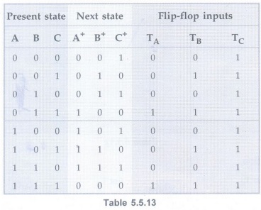
K-map simplification

Logic diagram
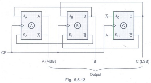
Example 5.5.12 Design and explain the working of a synchronous mod-3 counter. AU: May-03, Marks 16
Solution:
N = 3 and
Step 1:
Since 22> 3, n = 2 i.e. flip-flops needed = 2.
Step 2:
Flip-Flops used : JK
Step 3:
Transition table
Step 4:
K-map simplification
Step 5:
Logic diagram
Example 5.5.13 Design and explain the working of mod-7 counter. AU: Dec.-03, Marks 8
Solution :
Step 1:
N = 7, and since 23>7, n = 3 i.e. Flip-Flops needed = 3
Step 2:
Flip-Flops used : JK
Step 3:
Transition table
Step 4:
K-map simplification
Step 5:
Logic diagram
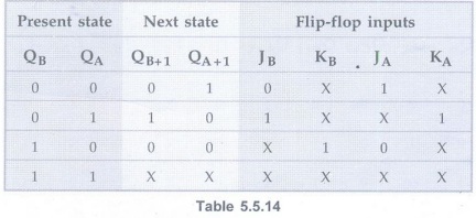
Example 5.5.14
Design a synchronous counter with states 0, 1, 2, 3, 0, 1…………. using JK FFs. AU:
May-04, Marks 16
Solution :
Step 1:
Here, N = 4 and since 22 ≥ 4 we need 2 Flip-Flops
Step 2:
Flip-Flops to be used : JK
Step 3:
Transition table
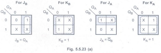
Step 4:
K-map simplification
Step 5:
Logic diagram
Example 5.5.15 Design a 3-bit binary counter using T flip-flop that has a repeated sequence of six states. 000-001-010-100-101-110. Give the state table, state diagram and logic diagram. Next states for unused states should be 000. AU: Dec.-07, Marks 16
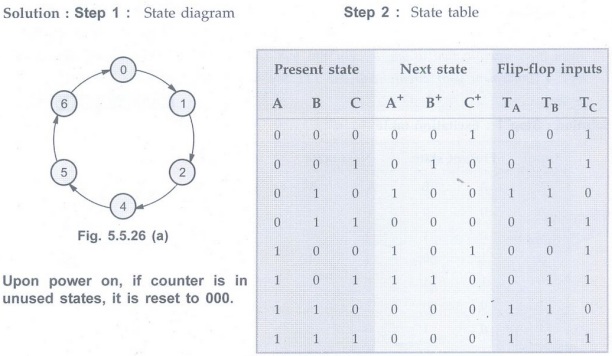
Step 3:
K-map simplification
Step 4:
Logic diagram
Example 5.5.16
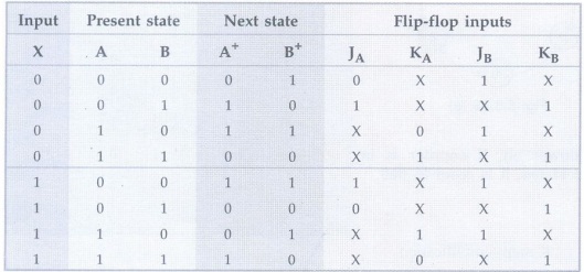
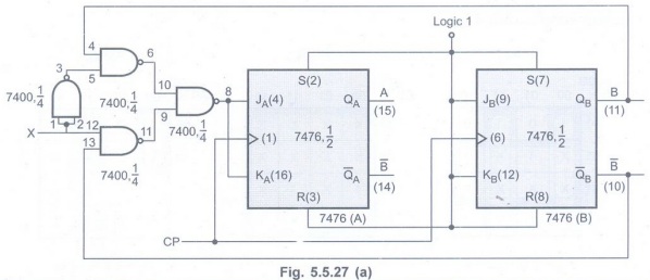
Design a synchronous up/down counter that will count up from zero to one to two
to three and will repeat whenever an external input x is logic 0, and will
count down from three to two to one to zero and will repeat whenever the
external input x is logic 1. Implement your circuit with one TTL SN74LS76
device and one TTL SN74LS00 device. AU May-10, Marks 12
Solution: Step 1:
Excitation table
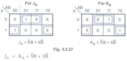
Step 2:
K-map simplification
Step 3:Logic
diagram
We can implement combinational logic
circuit for JA and KA input using NAND-NAND logic, as shown in the Fig. 5.5.27.
Example 5.5.17
Design a synchronous counter using JK flip-flop to count the following sequence
: "1-3-15-5-8-2-0-12-6-9". AU May-11, Marks 16
Solution:
Since counter has 0-15 states we need 4 flip-flops.
Excitation table
K-map simplification
Logic diagram
Examples for Practice
Example 5.5.18
Design a Mod-6 synchronous counter using JK flip-flops.
Example 5.5.19
Find a modulo-6 gray code using K-map and design the correspondingcounter.
Example 5.5.20 Design and explain the working of a mod-11 counter. AU May-05, Marks 8
Example 5.5.21
Using D flip-flops, design a synchronous counter which counts in the sequence,
000, 001, 010,011, 100, 101, 110, 111, 000. AU May-14, Marks 8
Example 5.5.22
Design a modulo-12 up synchronous counter using T flip-flops and draw the
circuit diagram.
Digital Principles and Computer Organization: Unit II (d): Counters : Tag: : Counters - Digital Principles and Computer Organization - Design of Synchronous Counters
Related Topics
Related Subjects

Digital Principles and Computer Organization
CS3351 3rd Semester CSE Dept | 2021 Regulation | 3rd Semester CSE Dept 2021 Regulation