Digital Principles and Computer Organization: Unit II (d): Counters
Design of Ripple (Synchronous) Counters
Counters - Digital Principles and Computer Organization
Choose the type of flip-flops to be used: T or JK. If T flip-flops are used connect T input of all flip-flops to logic 1. If JK flip-flops are used connect both J and K inputs of all flip flops to logic 1.
Design of Ripple
(Asynchronous) Counters
AU: Dec.-04, May-06, 09, 11
Steps involved in the design of
asynchronous counter
1. Determine the number of flip-flops
needed.
2. Choose the type of flip-flops to be
used: T or JK. If T flip-flops are used connect T input of all flip-flops to
logic 1. If JK flip-flops are used connect both J and K inputs of all flip
flops to logic 1.
Such connection toggles the flip-flop
output on each clock transition.
3. Write the truth table for the
counter.
4. Derive the reset logic by K-map
simplification.
5. Draw the logic diagram.
Example 5.3.1
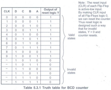
Design BCD ripple counter using JK flip-flop.
AU Dec.-04, May-06, 11, Marks 16
Solution:
Step 1:Determine
the number of flip-flops needed. The BCD counter goes through states 0-9, i.e.
total 10 states. Thus, N 10 and for 2n > N, we need n = 4, i.e. 4
flip-flops required.
Step 2:Type
of flip-flops to be used: JK
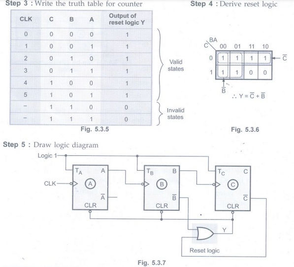
Step 3:Write
the truth table for the counter
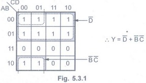
Step 4:
Derive reset logic
Step 5:
Draw logic diagram.

Example 5.3.2
Design a 3-bit asynchronous ripple counter using T flip-flops and explain
its operation. AU May-09, Marks 16
Solution:
The Fig. 5.3.3 shows a asynchronous ripple counter T using flip-flops. As shown in
Fig. 5.3.3, the clock input of only first stage flip-flop. The clock input
of the second stage flip-flop is
triggered by the QA output of the first stage and third stage
flip-flop is triggered by the QA output of second stage. Because of
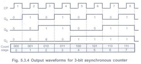
the inherent propagation delay time through a flip-flop, a transition of the
input clock pulse and a transition of the QA output of previous stage
can never occur at exactly the same time. Therefore, flip-flops are never
simultaneously triggered, which results in asynchronous counter operation.
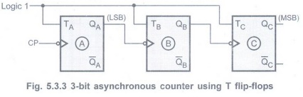
Since, T input is connected to logic 1
each flip-flop toggles at clock input. The Fig. 5.3.4 shows the timing diagram
for 3-bit asynchronous counter.
Example 5.3.3
Design mod 6 ripple counter using T flip-flops.
Solution :
Step 1:Determine
the number of flip-flop required. Here, counter goes through 0 - 5 states,
i.e., total 6 states. Thus N = 6 and for 2n> N we need n = 3,
i.e, 3 flip-flops
Step 2: Type of flip-flops to be used: T
Example for Practice
Example 5.3.4:
Show that a BCD ripple counter can be constructed using a 4-bit binary ripple
counter with asynchronous clear and a NAND gate that detects the occurrence of
count 1010.
Review Questions
1. Explain the working of BCD ripple counter with timing diagrams. AU: Dec.-04, Marks 16
2. Design mod 5 ripple counter using T flip-flops.Digital Principles and Computer Organization: Unit II (d): Counters : Tag: : Counters - Digital Principles and Computer Organization - Design of Ripple (Synchronous) Counters
Related Topics
Related Subjects

Digital Principles and Computer Organization
CS3351 3rd Semester CSE Dept | 2021 Regulation | 3rd Semester CSE Dept 2021 Regulation