Digital Principles and Computer Organization: Unit I: Combinational Logic
Demultiplexers
Combinational Logic - Digital Principles and Computer Organization
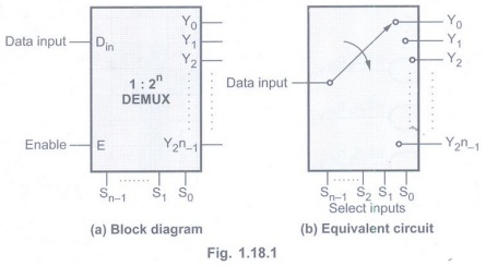
A demultiplexer is a circuit that receives information on a single line and transmits this information on one of 2n possible output lines.
Demultiplexers
AU:
May-11
• A demultiplexer is a circuit that
receives information on a single line and transmits this information on one of 2n
possible output lines.
• The selection of specific output line
is controlled by the values of n selection lines.
• The Fig. 1.18.1 shows the block
diagram of a demultiplexer. It has one input data line, 2n output
lines, n select lines and one enable input.
Differentiate between Multiplexer and
Demultiplexer

Types of Demultiplexers
1: 4
Demultiplexer
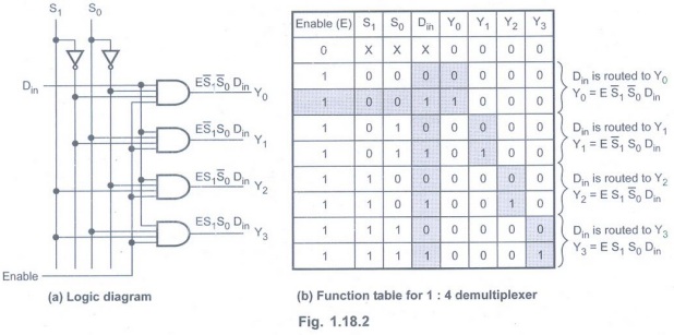
• Fig.1.18.2 shows 1 : 4 demultiplexer.
• The single input variable Din
has a path to all four outputs, but the input information is directed to only
one of the output lines depending on the select inputs.
• Enable input should be high to enable
demultiplexer.
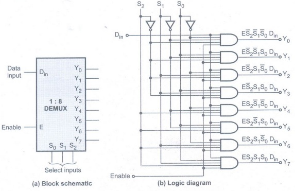
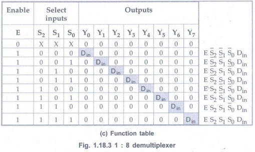
1 :8
Demultiplexer
• The Fig. 1.18.3 shows 1 : 8
demultiplexer.
• The single input data Din
has a path to all eight outputs, but the input information is directed to only
one of the output lines depending on the select inputs.
Expanding Demultiplexer
• To provide larger output needs we can cascade two or more demultiplexer to get demultiplexer with more number of output lines. Such a connection is known as demultiplexer tree.
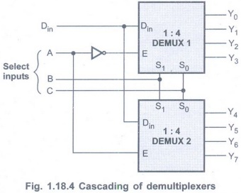
Example 1.18.1 Design
1: 8 demultiplexer using two 1 : 4 demultiplexers.
Solution:
Step 1: Connect
Din signal to in Din put of both the demultiplexers.
Step 2: Connect
select lines B and C to select lines S1 and S0 of the
both demultiplexers, respectively.
Step 3: Connect
most significant select line (A) such that when A = 0 DEMUX 1 is enabled and
when A = 1 DEMUX 2 is enabled.
Example 1.18.2
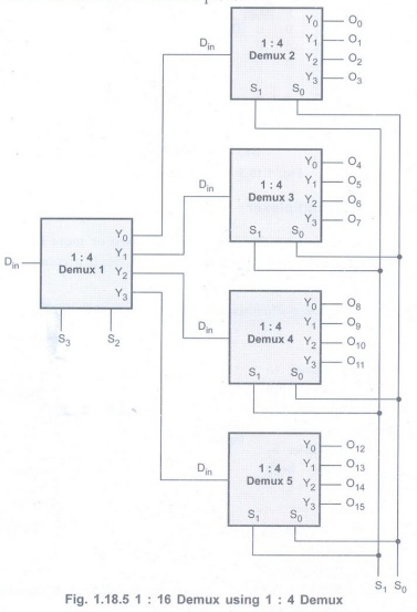
Implement 1: 16 demultiplexer using 1 : 4 demultiplexers.
Solution:
The 1: 16 demultiplexer has 16 outputs. To select one of the 16 output, the
circuit needs 4 (24= 16) select lines. Each 1 : 4 demultiplexer
requires 2 select lines.
Step 1: Connect
two least significant select lines (S1, S0) to select
lines of four 4: 1 demultiplexer.
Step 2: Connect
one more 4 : 1 demultiplexer such that its four outputs are routed to the data
inputs of the four demultiplexers. Connect higher select lines (S3 ,S2)
to the select lines of this demultiplexer.
Example for Practice
Example 1.18.3:
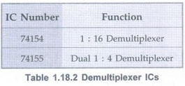
Construct 1 to 32 demultiplexer using two 74 X 154 ICs.
(1: 16 DEMUX).
Implementation of Combinational Logic using Demultiplexer
Example 1.18.4
Implement full subtractor using demultiplexer.
Solution:
Step 1:
Write the truth table of full subtractor.
Step 2: Represent
output of full-subtractors in minterm form.
• For full subtractor, difference D
function can be written as
D = f(A, B, C) =∑m (1, 2, 4, 7) and Bout
function can be written as,
Bout =F (A, B, C)= ∑m (1, 2,
3, 7)
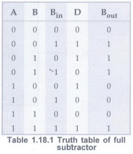
Step 3: Logically
OR the outputs corresponding to minterms.
With Din input 1,
demultiplexer gives minterms at the output so by logically ORing required
minterms we implement Boolean functions for full subtractor.
• Fig. 1.18.6 shows the implementation
of full subtractor using demultiplexer.

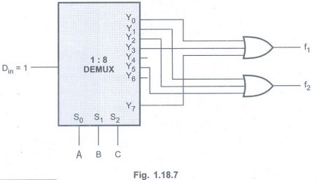
Example 1.18.5
Implement the following functions using demultiplexer :
f1 (A, B, C) = ∑m(0, 3, 7)
f2 (A, B, C) =∑m(1, 2, 5).
Solution :
f1 (A, B, C) = Σm (0, 3, 7)
f2 (A, B, C) = Σ m (1, 2, 5)
Implementation using 1: 8 demultiplexer.
Examples for Practice
Example 1.18.6
Implement full adder using demultiplexer. AU: May-11, Marks 5
Example 1.18.7
Implement the following functions using demultiplexer
f1 (A, B, C) = ∑m (1, 5, 7),
f2 (A, B, C) = ∑m (3, 6, 7)
Applications of Demultiplexer
1. It can be used as a decoder.
2. It can be used as a data distributor.
3. It is used in time division multiplexing
at the receiving end as a data separator.
4. It can be used to implement Boolean
expressions.
Demultiplexer ICs
Digital Principles and Computer Organization: Unit I: Combinational Logic : Tag: : Combinational Logic - Digital Principles and Computer Organization - Demultiplexers
Related Topics
Related Subjects

Digital Principles and Computer Organization
CS3351 3rd Semester CSE Dept | 2021 Regulation | 3rd Semester CSE Dept 2021 Regulation