Basic Electrical and Electronics Engineering: Unit IV: Digital Electronics
Decoder
Operation, Block diagram, Logic Circuit, Example, Truth Table | Digital Electronics
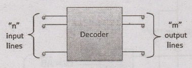
A decoder is a combinational circuit. It has n input and to a maximum m = 2n outputs. Decoder is identical to a demultiplexer without any data input.
DECODER
A
decoder is a combinational circuit. It has n input and to a maximum m = 2n
outputs. Decoder is identical to a demultiplexer without any data input. It
performs operations which are exactly opposite to those of an encoder.
Block diagram
Examples
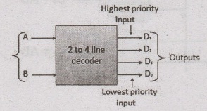
2
to 4 Line Decoder.
The
block diagram of 2 to 4 line decoder is shown in the fig. A and B are the two
inputs where D through D are the four outputs. Truth table explains the
operations of a decoder. It shows that each output is 1 for only a specific
combination of inputs.
Block diagram
Truth Table

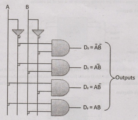
Logic Circuit
Basic Electrical and Electronics Engineering: Unit IV: Digital Electronics : Tag: : Operation, Block diagram, Logic Circuit, Example, Truth Table | Digital Electronics - Decoder
Related Topics
Related Subjects

Basic Electrical and Electronics Engineering
BE3251 2nd semester Mechanical Dept | 2021 Regulation | 2nd Semester Mechanical Dept 2021 Regulation

Basic Electrical and Electronics Engineering
BE3251 2nd Semester CSE Dept 2021 | Regulation | 2nd Semester CSE Dept 2021 Regulation