Digital Principles and Computer Organization: Unit II (b): Analysis & Design of Clocked Sequential Circuits
Clocked Sequential Circuits
Analysis & Design of Clocked Sequential Circuits - Digital Principles and Computer Organization
In synchronous or clocked sequential circuits, clocked flip-flops are used as memory elements, which change their individual states in synchronism with the periodic clock signal.
Clocked Sequential
Circuits
AU: May-05,09, Dec.-07,08,10,14
• In synchronous or clocked sequential
circuits, clocked flip-flops are used as memory elements, which change their
individual states in synchronism with the periodic clock signal.
• Therefore, the change in states of
flip-flops and change in state of the entire circuit occurs at the transition
of the clock signal.
• The states of the output of the
flip-flop in the sequential circuit gives the state of the sequential circuit.
Present state:
The status of all state variables, at some time t, before the next clock edge,
represents condition called present state.
Next state:
The status of all state variables, at some time, t + 1, represents a condition
called next state.
The synchronous or clocked sequential
circuits are represented by two models.
• Moore model: The output depends
only on the present state of the flip-flops.
• Mealy model: The output depends
on both the present state of the flip-flop(s) and on the input(s).
Moore Model
• When the output
of the sequential circuit depends only on the present state of the flip-flop,the sequential
circuit is referred to as Moore model.
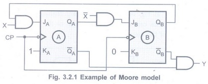
• Let us see one example of Moore model.
Fig. 3.2.1 shows a sequential circuit which consists of two JK flip-flops and
AND gate. The circuit has one input X and one output Y.
• As shown in the Fig. 3.2.1, input X is
used to determine the inputs of the flip-flops. It is not used to determine the
output. The output is derived using only present states of the flip-flops or
combination of it (in this case Y = QAQB).
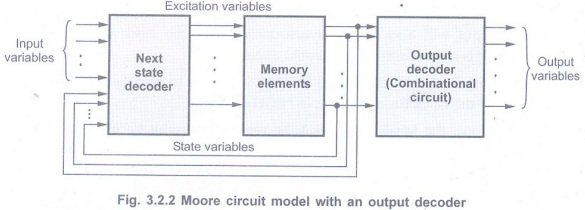
• In general form the Moore model can be
represented with its block schematic as shown in Fig. 3.2.2.
Mealy Model
• When the output of the sequential
circuit depends on both the present state of flip-flop(s) and on the input(s),
the sequential circuit is referred to as Mealy model.
• Fig. 3.2.3 shows the sample Mealy
model. As shown in the Fig. 3.2.3, the output of the circuit is derived from
the combination of present state of flip-flops and input(s) of the circuit.
• Looking at Fig. 3.2.3, we can easily
realize that, changes in the input within the clock pulses can not affect the
state of the flip-flop. However, they can affect the output of the circuit.
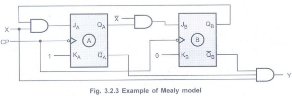
• Due to this, if the input variations
are not synchronized with the clock, the derived output will also not be
synchronized with the clock and we get false output (as it is a synchronous
sequential circuit).
• The false outputs can be eliminated by
allowing input to change only at the active transition of the clock (in our
example HIGH-to-LOW).
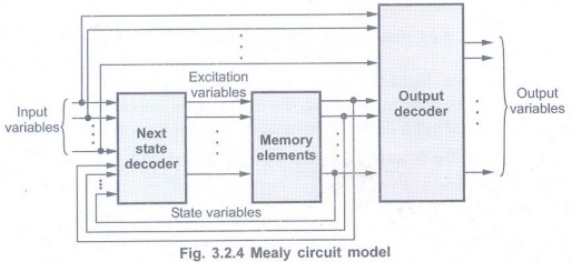
• In general form the Mealy model can be
represented with its block schematic as shown in Fig. 3.2.4.
Moore Vs Mealy Circuit Models
Representation of Sequential Circuits
State Diagram
For Mealy circuit
• State diagram is a pictorial
representation of a behaviour of a sequential circuit. Fig. 3.2.5 shows a state
diagram.
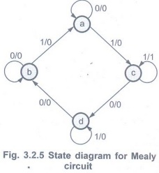
• The state is represented by the circle,
and the transition between states is indicated by directed lines connecting the
circles.
• A directed line connecting a circle
with itself indicates that next state is same as present state.
• The state variable inside each circle
identifies the state represented by the circle.
• The directed lines are labelled with two binary numbers separated by a symbol '/'. The input value that causes the state transition is labelled first and the output value during the present state is labelled after the symbol '/'.
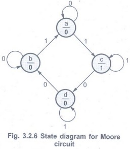
For Moore circuit
• In case of Moore circuit, the directed
lines are labelled with only one binary number representing the state of the
input that causes the state transition.
• The output state is indicated within
the circle, below the present state because output state depends only on
present state and not on the input.
• Fig. 3.2.6 shows the state diagram for
Moore circuit.
State Table
• Representation of state machine using
relationship between input(s), present state, next state and the output(s) in
the tabular form is known as state table.
• Table 3.2.2 (a) shows the state table
for the state diagram shown in Fig. 3.2.5.
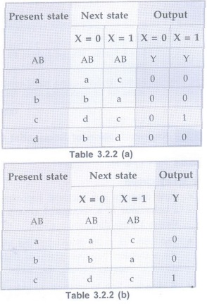
• It represents relationship between
input, output and flip-flop states.
• It consists of three sections labeled
present state, next state and output.
• The present state designates the state
of flip-flops before the occurrence of a clock pulse.
• The next state is state of the
flip-flop after the application of a clock pulse, and the output section gives
the values of the output variables during the present state.
• Both the next state and output sections
have two columns representing two possible input conditions: X = 0 and X = 1.
• In case of Moore circuit the output section has only one column since output does not depend on input. The Table 3.2.2 (b) shows the state table for Moore circuit whose state diagram is shown in Fig. 3.2.6.
Transition Table
• A transition table takes the state
table one step further. The state diagram and state table represent state using
symbols ornames.
• In the transition table specific state
variable values are assigned to each state.
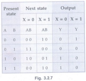
• Assignment of values to state variables
is called State assignment.
• Like state table transition table also
represents relationship between input, output
and flip-flop states. The Fig. 3.2.7
shows the transition table.
Here, AB are the state variables. The AB
= 00 represents one state, AB = 01 represents second state and so on.
Review Questions
1. What is a state?
2. What is Moore machine? AU: Dec.-07,
Marks 2
3. What is a Mealy machine? Give an
example. AU May-05, Dec.-08, Marks 2
4. Compare Moore and Mealy circuits. AU
May-05, 09, Dec.-08, 10, 14, Marks 4
5. What is transition table?
Digital Principles and Computer Organization: Unit II (b): Analysis & Design of Clocked Sequential Circuits : Tag: : Analysis & Design of Clocked Sequential Circuits - Digital Principles and Computer Organization - Clocked Sequential Circuits
Related Topics
Related Subjects

Digital Principles and Computer Organization
CS3351 3rd Semester CSE Dept | 2021 Regulation | 3rd Semester CSE Dept 2021 Regulation