Digital Principles and Computer Organization: Unit II (b): Analysis & Design of Clocked Sequential Circuits
Analysis of Clocked Sequential Circuits
Analysis & Design of Clocked Sequential Circuits - Digital Principles and Computer Organization
The behaviour of a sequential network is determined from the inputs, the outputs, a and the states of its flip-flops. The analysis of sequential circuit consists of obtaining a table or a diagram for the time sequence of inputs, outputs and internal states.
Analysis of Clocked
Sequential Circuits
AU: Dec.-03,06,07,15,19,
May-07,10,11,15,19
• The behaviour of a sequential network
is determined from the inputs, the outputs, a and the states of its flip-flops.
• The analysis of sequential circuit
consists of obtaining a table or a diagram for the time sequence of inputs,
outputs and internal
states.
Consider the sequential circuit to be
analysed as shown in Fig. 3.3.1.
Let us see the steps to analyze the
given synchronous sequential circuit.
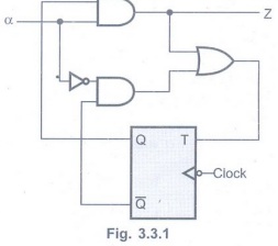
1. Determine the flip-flop input
equations and the output equations from the sequential circuit.
Z = α Q
T = α Q + ᾱ ![]()
2. Derive the transition equation.
The transition equation for T flip-flop
is
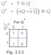
3. Plot the next step map for each
flip-flop

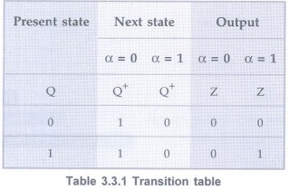
4. Plot the transition table
Note If circuit
consists of more than one flip-flop we have to combine the map of flip-flop to
derive the transition table. (Refer next example)
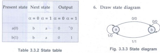
5. Draw the state table
The transition table shown in Table
3.3.1 can be converted into state table as sown in Table 3.3.2. Here, new
symbols to binary codes are assigned. They area = 0, b = 1.
Examples for Understanding
Example 3.3.1 Construct
the transition table, state table and state diagram for the Moore sequential
circuit shown in Fig. 3.3.4 (a):

Solution:
1. Determine the flip-flop
input equations and the output equations from the sequential circuit.
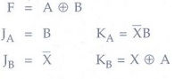
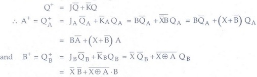
2. Derive the transition equations.
The transition equations for JK
flip-flops can be derived from the characteristic equation of JK flip-flop as
follows:
We know that for JK flip-flop
3.Plot a next-state maps for each
flip-flop.
The next-state maps are:
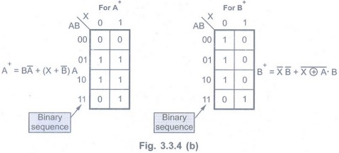
4.Plot the transition table.
The transition table can be formed by
combining the above two maps. The Table 3.3.3 shows the transition table.
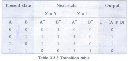
Note For Moore
sequential circuit output only depends on present state and not on the input.
5. Draw the state table
By assigning a = 0 0, b = 01, c = 10 and
d = 11 we can write state table from the transition table as shown.
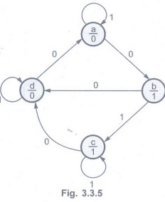
6. Draw state diagram
From the state table we can draw state
diagram as shown in Fig. 3.3.5
Note In case of Moore
model, the directed lines are labelled with only one binary number representing
the state of the input that causes the state transition. The output state is
indicated within the circle, below the present state because output state
depends only on present state and not on the input.
Example 3.3.2
A sequential circuit with 2D FFs A and B and input X and output Y is specified
by the following next state and output equations.
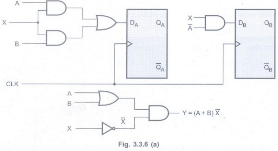
A (t+1)=AX+BX
B(t+1) = A'X
Y = (A+B) X'
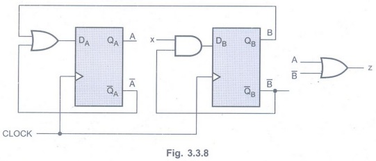
i) Draw the logic diagram of the
circuit.
ii) Derive the state table.
iii) Derive the state diagram.AU
:Dec-06,15, May-07, Marks 16
Solution :
i)Logic diagram
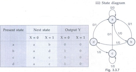
ii) State table
Step 1:Plot the next-state map for each flip-flop.
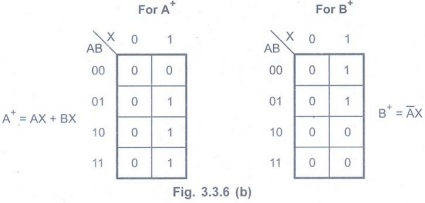
Step 2:Plot
the transition table.
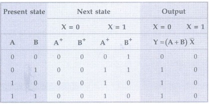
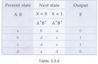
Step 3:Draw
the state table.
By assigning a = 00, b = 01, c = 10 and
d=11 we can write state table from the transition table.
Example 3.3.3:
A sequential circuit with two D flip-flops A and B, one input x, and one output
z is specified by the following next state and output equations:
A(t + 1) = A'+B, B(t + 1) = B'x, z = A +
B',
1) Draw the logic diagram of the circuit
2) Derive the state table
3) Draw the state diagram of the
circuit. AU May-15, Marks 4+3+3
Solution :
1. Logic Diagram
2. State Table
Step 1:Plot the next-state map for each flip-flop.
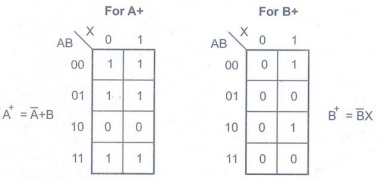
Step 2:Plot
the transition table
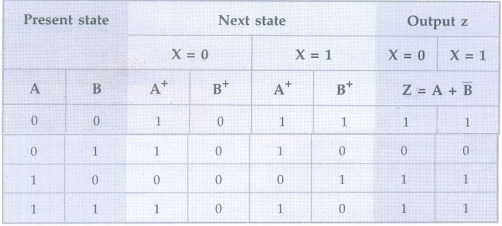
Step 3:Draw
the state table
By assigning a = 00, b = 01, c = 10 and
d =11we can write state table from thetransition table.
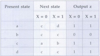
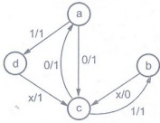
3. State diagram
Example 3.3.4
A sequential circuit has four FFs ABCD and an input X is described by the
following state equations.

B (t + 1) = A
C (t + 1) = B
D (t + 1) = C
i) Obtain the sequence of states when X
= 1, starting from state ABCD = 0001.
ii) Obtain the sequence of states when X = 0 starting from state ABCD 0000. AU: Dec.-06, May-07, Marks 16
Solution:
i) X = 1 and Initially ABCD = 0001.
A B C D E<= 1000,0100, 0010, 1001,
1100, 0110, 1011, 0101, 1010, 1101,1110,
1111, 0111, 0011, 0001
ii) X = 0 and Initially ABCD = 0000
A B C D <= 1000, 1100, 1110, 0111,
1011, 1101, 0110, 0011, 1001, 0100, 1010, 0101, 0010, 0001, 0000
Example 3.3.5 A sequential circuit has one flip-flop Q, two inputs x and y, and one output S. It consists of a full adder circuit connected to a D flip-flop, as shown below. Derive the state table and state diagram of the sequential circuit. AU Dec.-07, Marks 12
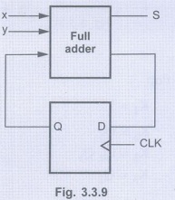
Solution :
Step 1:Derive
the state table

Example 3.3.6
For the circuit shown in Fig. 3.3.11, write down the state table and draw the
state diagram and analyze the operation. AU: May-10, Marks 16
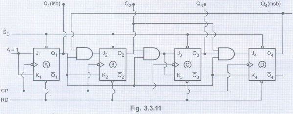
Solution :
Step 1:Inputs
for each flip-flop
J1= 1 K1 = 1
J2= Q1 Q4 K2
= Q1
J3= Q2 Q1 K3= Q2
Q1
J4= Q1 Q2
Q3 K3 = Q1
Step 2:
Transition equations for each flip-flop
For JK flip-flop
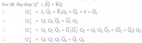
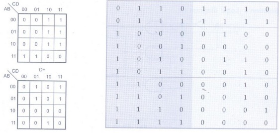
Step 3:Next
state maps for each flip-flop
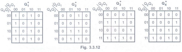
Step 4:
Transition table
Step 5:
State assignment
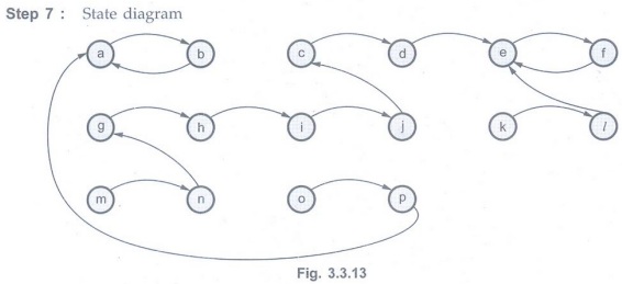
a = 0000,
b=0001,
C = 0010,
d = 0011,
e = 0100,
f = 0101,
g= 0110,
h = 0111,
i = 1000,
j = 1001,
k = 1010,
1 = 1011,
m = 1100,
n = 1101,
0 = 1110,
p = 1111
Step 6:
State table

Step 7:State
diagram
Example 3.3.7
A synchronous counter with four JK flip-flops has the following connections:
JA = KA = 1, JB
= QA ![]() D, KB = QA
D, KB = QA
JC = KC = QA
QB
JD = QA QB
QC and KD QA
Determine the modulus n of the counter and draw the output waveforms of the
same. AU May-11, Marks 16

Counter goes through states: 0 - 8 - 4 -12
- 2 -10 - 6 – 14 – 1 – 9 – 0

Thus is a modulus 10 counter.
Example 3.3.8
A sequential circuit with two D flip-flops A and B, two inputs X and Y and one
output z is specified by the following input equations:
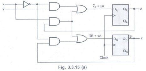
A(t + 1) = x'y + xA, B(t + 1) = x'B +
xA, z = B
Draw the logic diagram of the circuit.
Derive the state table and state diagram and state whether it is a Mealy or a
Moore machine. AU May-19, Marks 8
Solution:
Logic diagram :
State table :
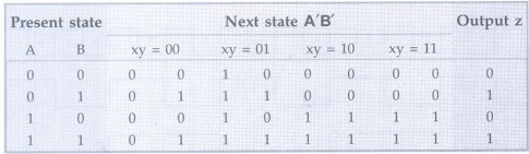
State assignment:
00→a, 01 → b, 10 → c and 11 → d
State diagram:
For this sequential circuit output is a
function of present state only and hence it is a Moore machine.
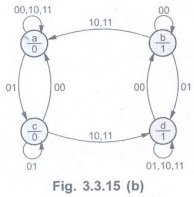
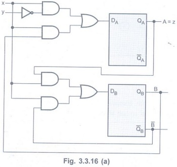
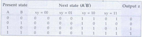
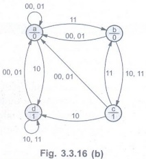
Example 3.3.9
A sequential circuit with two D flip-flops A and B, two inputs x and y; and one
output z is specified by the following next-state and output equations: A(t +
1) = xy' + xB, B(t + 1) = xA + xB', z = A
i) Draw the logic diagram of the
circuit. AU: Dec.-19, Marks 8
ii) List the state table for the
sequential circuit Marks 4
iii) Draw the corresponding state diagram Marks 3
Solution:
Logic diagram :
State table :
State assignment:
00→a, 01 → b, 10 → c, 11 → d
State diagram:
Examples for Practice
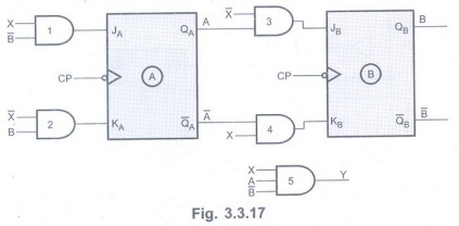
Example 3.3.10: Construct
the transition table, state table and state diagram for the Mealy sequential
circuit given in Fig. 3.3.17.
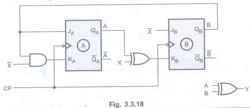
Example 3.3.11:
Derive the transition table, state table and state diagram for Moore sequential
circuit shown in Fig. 3.3.18.
Review Question
1. Explain the various steps in the
analysis of synchronous sequential circuits with suitable example. AU:
Dec.-03, Marks 8
Digital Principles and Computer Organization: Unit II (b): Analysis & Design of Clocked Sequential Circuits : Tag: : Analysis & Design of Clocked Sequential Circuits - Digital Principles and Computer Organization - Analysis of Clocked Sequential Circuits
Related Topics
Related Subjects

Digital Principles and Computer Organization
CS3351 3rd Semester CSE Dept | 2021 Regulation | 3rd Semester CSE Dept 2021 Regulation